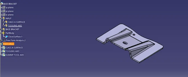
Week 8 - Challenge 1 - Base Bracket Design
Week 8 - Challenge 1 - Base Bracket Design:-
Create the Base Bracket Plastic component through the given Class-A surface. To begin with, the tooling axis for the given Class-A Surface should be created meeting the requirements of the draft angle and at the end perform the Draft analysis on the model.
NOTE:
- Tree Structure
- Ensure Proper Tree Structure
- Geometrical sets should have a proper name based on the sketches present inside of it
- All the sketches should be created under the Geometrical set
- Use the Close Surface feature to make a solid body from the surface.
- Publications: Use the publication option and publish the below
- Tooling Axis
- Class A, B, and C surface
Report:-
Objective:-
Main objective of this challange to create the Base bracket of plastic componet throughtout above given Class - A Surface ,by giving Tool axis and Draft analysis to make Class-A surface to thickness of solid base-bracket
Tooling axis:-Class - A Surface
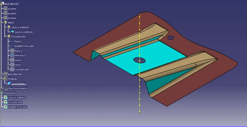
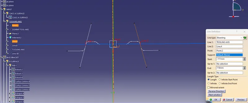
We should Observe the Class -A modeling Start with Fully developed the design to Tooling axis Above the base bracket of Tooling direction Z - Direction best for suitable for tooling axis initially. I created a dummy tooling axis on Z-axis by considering the reference point created in the middle of the circle.
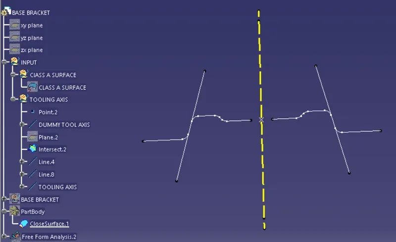
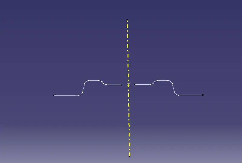
Biscting Line:-
DRAFT ANALYSIS:
To perform draft analysis, click on Insert Feature Draft Analysis
Once the draft analysis toolbar is opened, go to the display block and select the 'Analysis under the running point' command to check the angle for different sides (ribs and inclined plane angles) on the class A surface. The color scale on the bottom visualizes, whether the draft angle meets the requirements or not (3 deg) by indicating the colors Green, Blue and Red. Once the draft angle analysis was done, we need to align and fix the compass to the tooling axis of the class A surface.
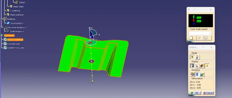
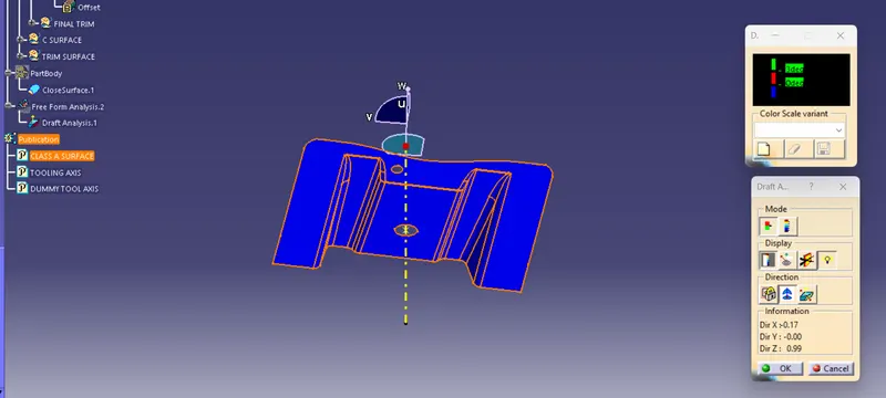
Before align the compas material customize view parameter selection only - material only
compas drage on the direction in Class -A surface Tooling direction in z -direction ,once we click ok draft analysis process. we can check draft angle in right side boxess
Draft allows for parts to release from the mold:-
- Draft is required on all parts in the direction of mold moment in order to allow parts to release or ejection from the mold properly
- Draft is the angle in which the part is tapered to allow it to release as the part cools,it tends to want to as the Shrink to the core side of the mold
- Adding draft help to the part to release most part or applications required a minium of 0.5 to 3 degree widly accpeted as the norm
CLASS B SURFACE:
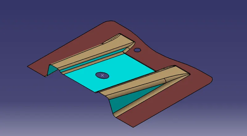
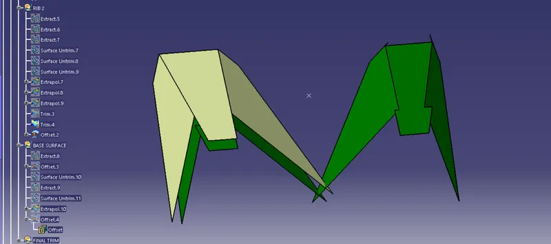
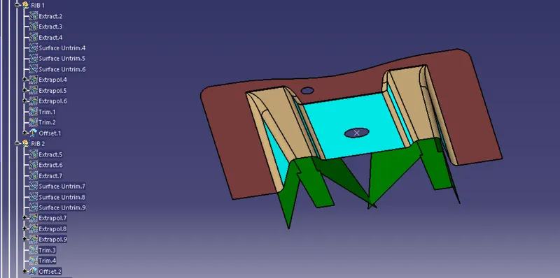
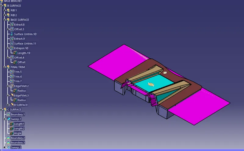
To create the class B surface, I considered the entire surface has 3 parts 'Rib-1, Rib-2, and Base surface'. If we directly offset the class A surface, fillets may lead to cause an error, to avoid the errors we need to extract the surfaces and untrim the extracted surfaces and extrapolate those untrimmed surfaces with point continuity. Now trim those extrapolated surfaces to the required shape. And finally, fillets were given to the final trim.
RIBS 1&2:-
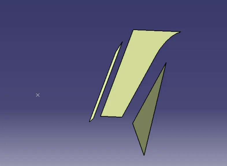
Surface Untrim :-
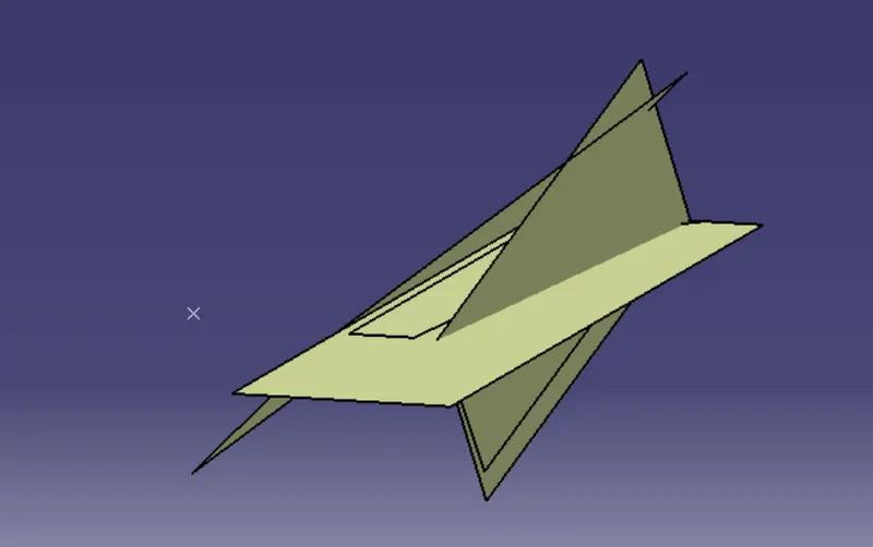
Extrapolate:-
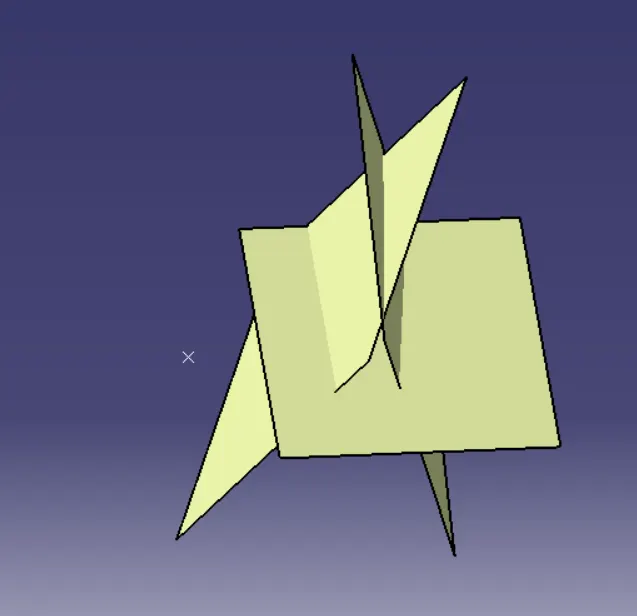
Parent children - Trimmed surface to Offset surface
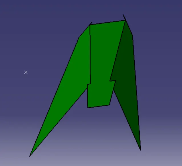
BASE SURFACE:-
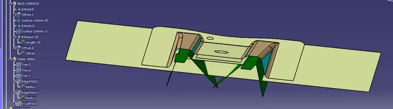
B SURFACE :-Final trim
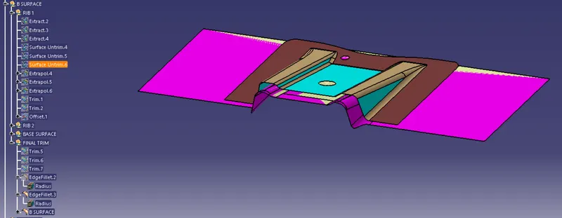
C Class - Surface:-
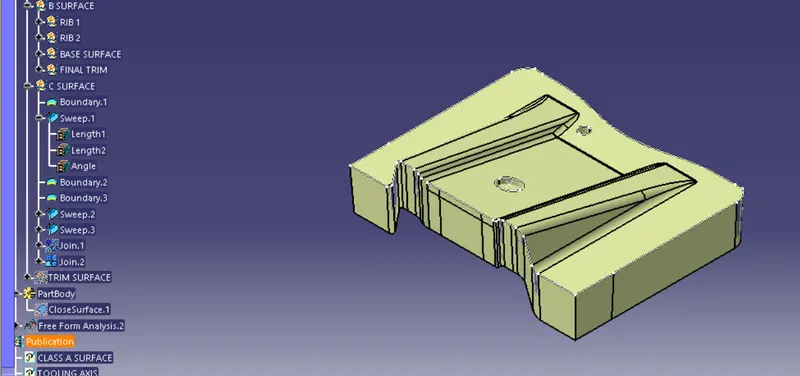
Final trim of part :-
FINAL SOLID SOLID CLOSED BODY:-