Week 8 - Challenge 1 - Base Bracket Design
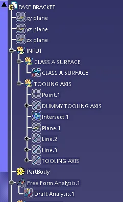
GEOMETRICAL TREE STRUCTURE
B SURFACE
C SURFACE
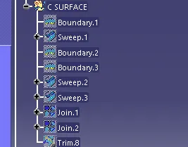
USE OF PUBLICATION AND CLOSED BODY
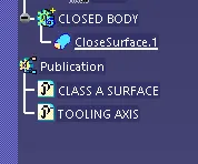
To perform draft analysis we need a tooling axis
TOOLING AXIS: The direction in which the mold or core and cavity opens is the tooling axis.
Creating a tooling axis
At first create a point with respect to the center hole. Then create a line from the point with respect to the z direction make sure to extend the line on both side
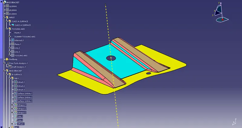
The line we just created was for reference to the main tooling axis
After creating a dummy tooling axis offest the plane in yz direction
Now with the plane created use the intersection option to create a intersection of the class A surface with recpect to the created plane
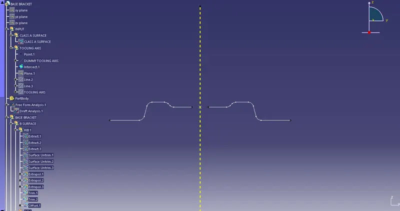
Now we got the intersection line with dummy tooling axis with this we are going to create the toolig axis
Create a line in the sideway joining the two inclined points on both sides
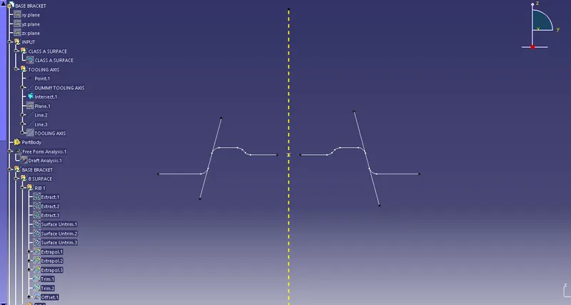
After the line is created use the bisecting line option
Then select the tow lines that we have just created and select the center point so that the tooling axis is accurate
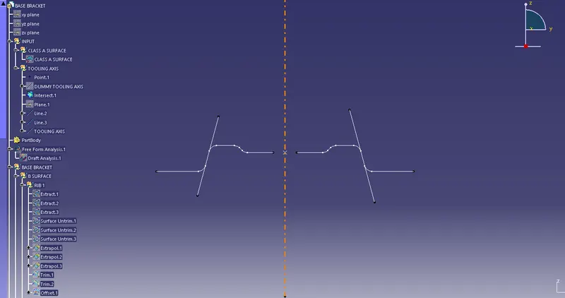
Now we got our tooling axis with respet to the inclined lines and the center point
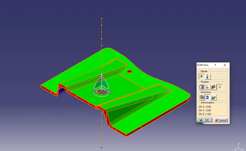
with this tooling axis we can now do the draft analysis
DRAFT ANALYSIS OF CLASS A SURFACE
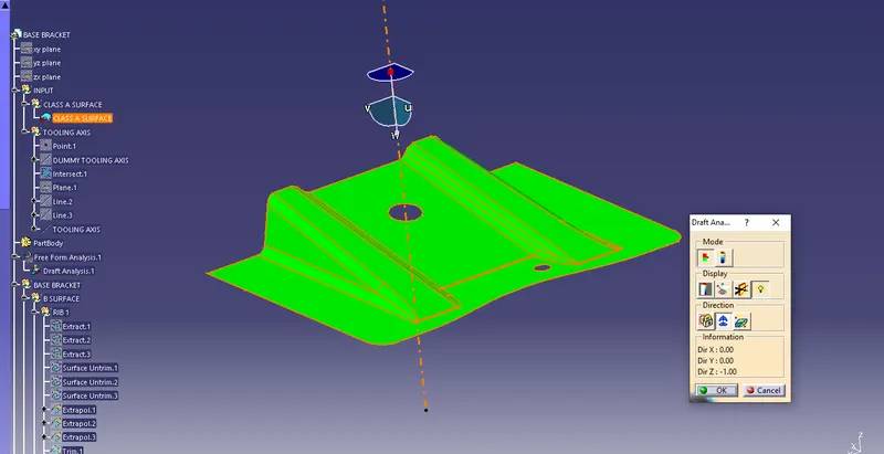
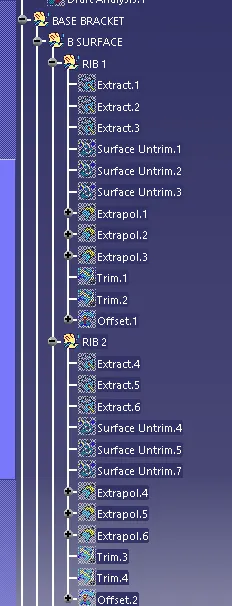
CLASS B SURFACE
By extracting the side of the class a surface we are now are now going to create the ribs of class B surface
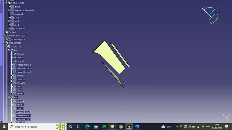
These are the side extracts of class A surface
we are now going to untrim each surface using the untrim option
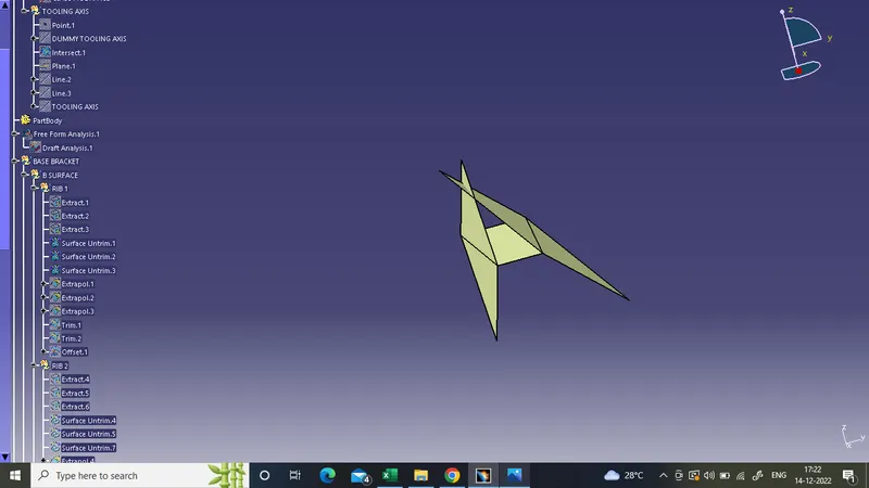
The surface looks like this after untrim
The length of the surface is not enough so we are going to extend the surface to a certain distance using Extrapolation
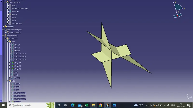
After this we are gonna trim the surface to the required shape using Class A reference
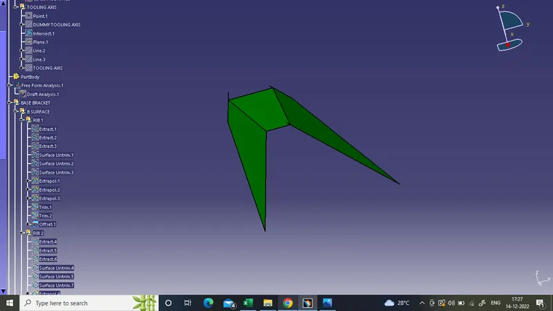
This is the required shape and is 2.5mm below the class A surface
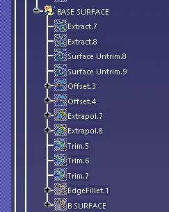
After this the base surface are extracted, untrimmed and extrapolated
Then they are trimmed with respect to the two ribs that we have created
After that the sharp edges are to be filleted we have to find the fillet value from the class A surface and add the thickness of the material to the fillet value
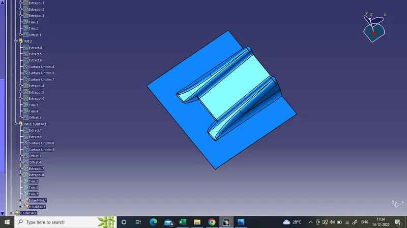
Class C Surface
Take the border of the class A surface and the use the sweep command to create a surface using the tooling axis

Then using the join command join the class A surface with the sweep you have created
After that trim the joined surface with respect to the class B surface
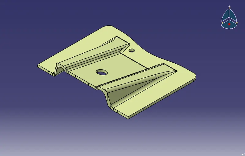
Now we got the required BASE BRACKET
ISOMETRIC VIEW
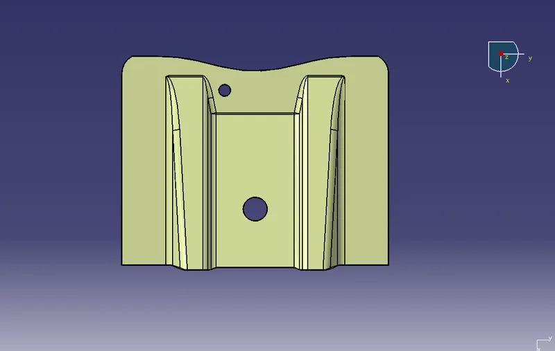
TOP VIEW
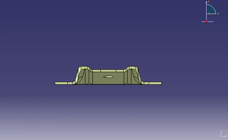
FRONT VIEW
Then use the closed body surface command to create a closed body surface
CLOSED BODY SURFACE
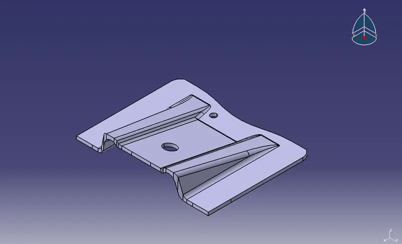
DRAFT ANALYSIAS OF FINAL PRODUCT