Week 8 - Challenge 1 - Base Bracket Design
Base Bracket Design
Class A surface Draft Analysis
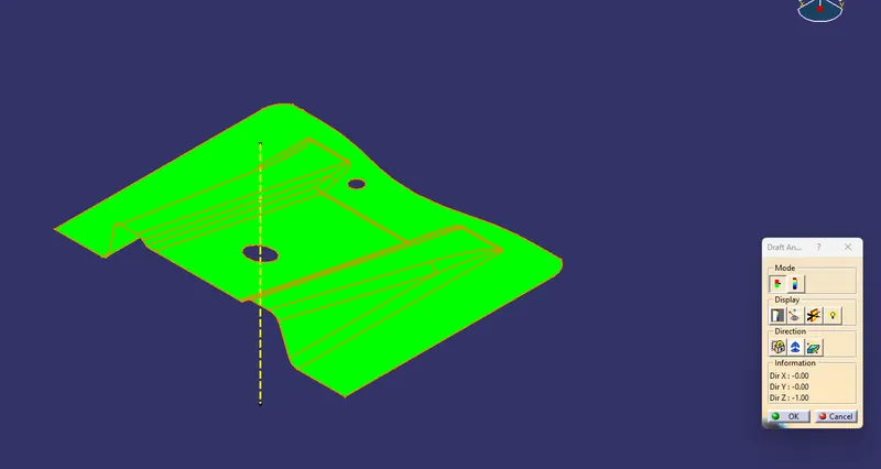
Final Product Draft Analysis
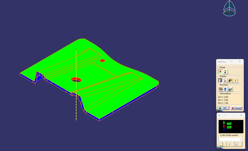
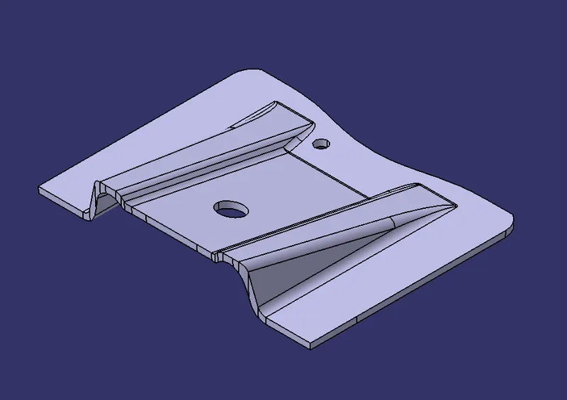
Solid Mode Views
Front View
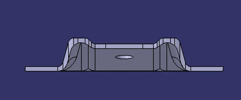
Side View
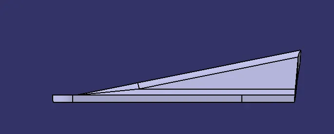
Top View
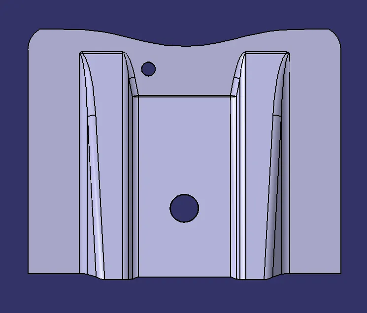
Isometric View
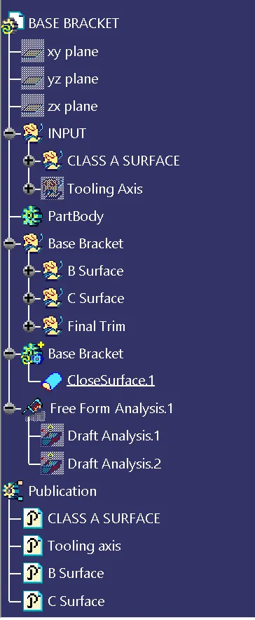
Structure Tree
Draft Analysis
What is Draft Analysis?
This analysis done on the CAD product to see whether the model is manufacturable or not. The plastic CAD model that are prepared in CAD software are manufactured in plastic mold, so it is necessary to check whether the part is manufacturable in mold or not. Because is part in not manufacturable in mold then CAD model fails.
What is Draft Angle?
If part has a 90° of draft, then it cannot be manufactured in plastic mold, because on removal of part it may worn or tear as it creates friction on the part removal and will cause damage to the part. The recommended draft angle is prescribed as 3°, but it can be less or more depend on the accuracy needed on the model. For screw holes draft angle should not be more as it will not give perfect fit for the screw.
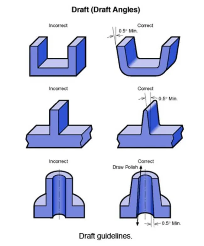
Draft using bisecting lines
In our project the drat direction is created using bisecting method. First, we analysis the model visually and then makes the draft direction using bisecting method. For analysis the draft direction we make sure the directions is possibly perpendicular to hole is we have any on the model, so that we do not have to introduce any other side core.
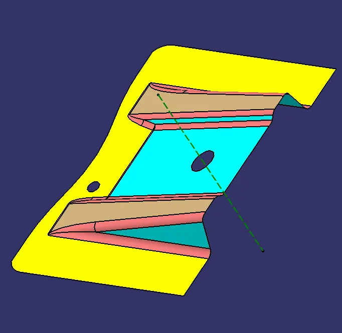
In our model the draft direction is made normal to the hole so that it is easy to manufacture. In order to get the direction, we use bisecting method.
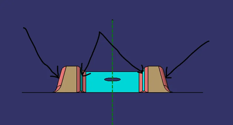
As we can see in the image, we have few angle walls in the model. So, we take the section of the model by creating the plane at the center of the hole and then taking the intersection the model.

After intersection we get the following results.
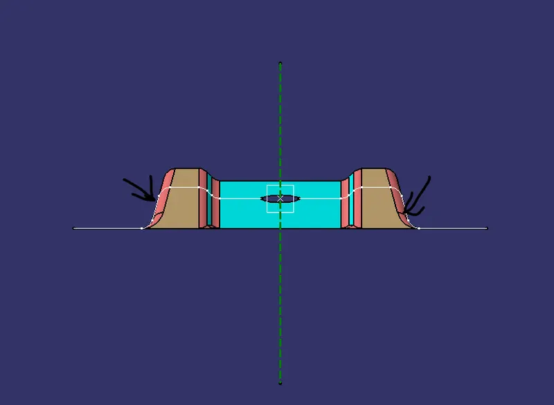
We can clearly see the walls are angled, so extend the lines of the angled wall so we can get the better view to create the bisecting line.
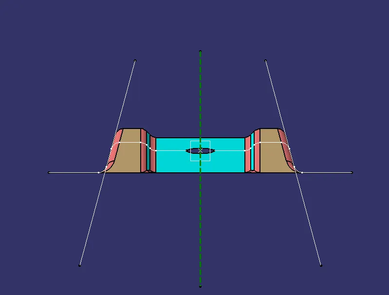
To create the bisecting line seethe image for better understanding,
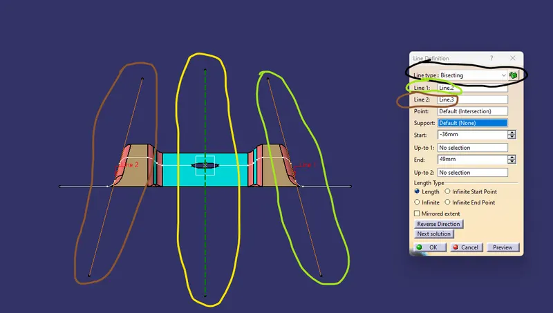
- Go to line command and select the bisecting in line type
- Select the two extended line to create the bisecting line (Green and brown color)
- This will create the bisecting line which is in the center of the two lines (yellow color)
This is the way of creating the bisecting line which is also our tooling direction for the model. This is the one way of creating the tool direction for draft analysis.
Draft Analysis:
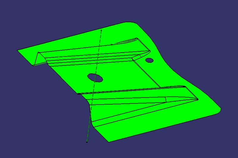
This is the result of draft analysis which is done on the class A surface, as we can see the model pass the draft analysis, which means our tooling direction is correct. If the color was red then our tooling direction need to be changed.