Week 8 - Challenge 1 - Base Bracket Design
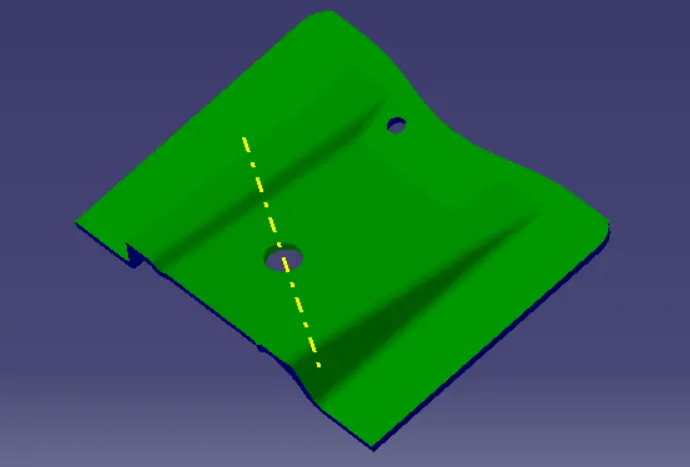
Aim - To create a Base Bracket Plastic Component through a given Class A Surface and perform Draft Analysis on the final plastic component.
Objective -
- To make sure that the model meets the requirements of the draft angle.
- To create the Tooling axis using bisecting method.
- To perform Draft analysis on the given Class A Surface.
- To create the required Class B and Class C surfaces.
- To obtain a solid body from the surface using Close Surface feature.
Theory -
Class A Surface -
- Class A surfaces are those surfaces which are curvature continuous while providing the simplest mathematical representation needed for the desired shape and does not have any undesirable waviness.
- The Class A surface is the used to begin the design of a product.
- All the further intricacies of the component are created based on the Class A surface.
Class B Surface -
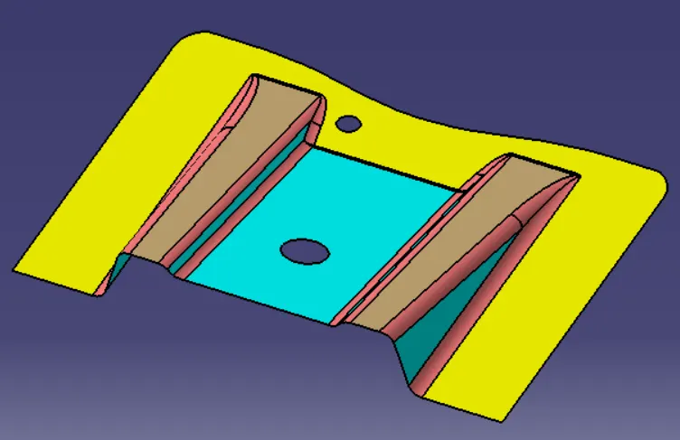
- The Class B surface is created from the Class A surface , keeping the thickness of the component in check.
- The Class B surface resembles an offsetted surface from the Class A.
Class C Surface -
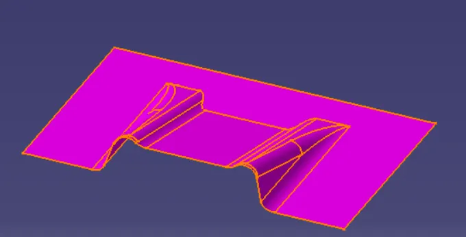
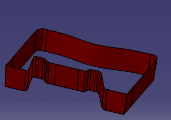
- The Class C surface is used to bind the Class A and Class B surface together inorder to form a closed surface.
Procedure -
1.Creating Tooling Axis -
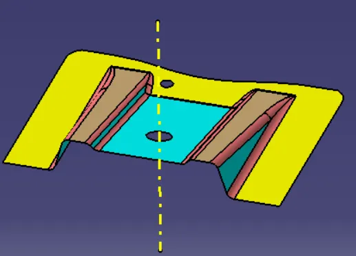
- Dummy Tooling Axis - A dummy Tooling Axis is created to take reference of Class A surface.
- Tooling Axis - The direction in which mold or core and cavity opens.For this need to check the all the possible direction and that axis clearing the all features of the product.Accordingly we are checking component wth X,Yand Z direction.After finding direction which is clearing all the features we checks features will caues trouble with draft(generally parallel features).To come over this we take bisecting line with these features and make our TOOLING AXIS.
2.Creating B surface -
- Now for Class B creation, we have extracted surface from Class A and untrimmed them to obtain the original parent surface.
- These surfaces are then offset to the required thickness.
- After offsetting, all the surfaces are trimmed into the required shape.
- Required fillets are given to the surfaces.
3.Creation Of C Surface -
- For creating this surface we have extracted the boundry of Class A using multi-extract and then converted to smooth curve.
- Now this smooth curve is swept along the draft direction with a 3deg draft.
4.Final Trims -
4.1. Class A + Class B
- To make sure that there is not any open boundry between class A and class C, we have used join option to created the single body. This is done to make sure that the parting line doesn't lie between the these two surfaces.
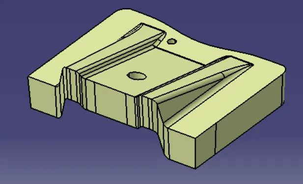
4.2.Class A + Class B + Class C -
- For this we have trimmed the above shown surface with the Class B surface using trim feature.
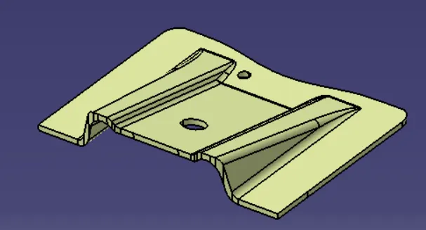
5. Final Product -
- After Closing the Surface we get the Final Product .
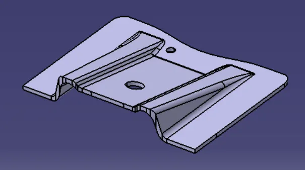
6.Draft Analysis -
Draft Analysis is used to check the whether the minimum draft of 3deg is maintained or not.