Week 8 - Challenge 1 - Base Bracket Design
Base Bracket Design – Plastic Component
AIM:
This report demonstrates the design of a Plastic Component - Bracket using industry principles such as Draft angles, Draft Analysis, Determining and implementing of Tooling Axis, Class A, Class B and Class C surfaces. The component is designed using CAD package CATIA V5.
The terms are briefly explained below:
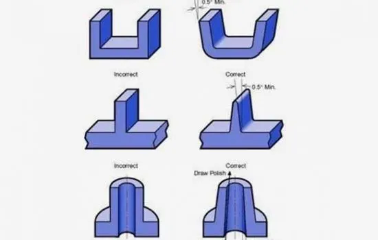
Draft:
Draft is an angular tapering given at the design stage to every Plastic Component that has to be manufactured. It is given in the direction of the Mold Movement. The Draft allows the parts to release easily from the mold without creating friction between the surface of component and the core and cavity plates.
When a Plastic component cools down inside the mold, the natural tendency of it is to shrink and attach to the core or cavity half. The movement of mold opening causes friction on the walls of the component as well as the core/cavity blocks. This reduces the life of the mold as well as the component itself. The component may also have rough surface finish as well as weak structure due to this. This problem can be solved by giving draft to the component.
Most applications require minimum draft angles of around 0.5º to 1º , however 3º draft angles are widely accepted for cost saving purpose. 7º Draft angles are given to textured surfaces like Instrument Panels. Minimum possible draft angles are given to screw bosses, ribs and stiffeners due to their critical nature.
Class- A Surface:
In automotive design, a class A surface is any of a set of freeform surfaces of high efficiency and quality. It is the visible aesthetic surface of any automotive component. Class A surface refers to those surfaces which are visible and abide to the physical meaning, in a product. This classification is primarily used in the automotive and increasingly in consumer goods industry. It is a requirement where aesthetics has a significant contribution. For this reason, the exterior of automobiles is deemed Class-A.
Class- B Surface:
Class B surfaces are Engineering Surfaces which are invisible to the eyes or often on the back side of the Class A surfaces. It is mainly the thickness of the component or Class A. These surfaces need to be designed as per the Class A surface i.e., the continuity, thickness of the component, functionality etc should be maintained. These surfaces include the main engineering features such as Screw bosses, Ribs, Snaps, Stiffeners and fixations. B surfaces also do not contain any aesthetic styling content and textures since it is not visible to eyes.
Class- C Surface:
Class C surfaces are connectors between Class A and B surfaces. This surface connects both A and B surfaces along the Tooling Axis. It contains the draft as per the design. Its is basically the thickened surface between both A and B surface.
MATERIAL USED:
POLYPROLENE
BENIFITS:
* IT CAN WITHSTAND HIGH TEMPERATURE
* IT HAS HIGH IMPACT
* MELTING POINT IS HIHG
* COST EFFECTIVE
PROCEDURE:
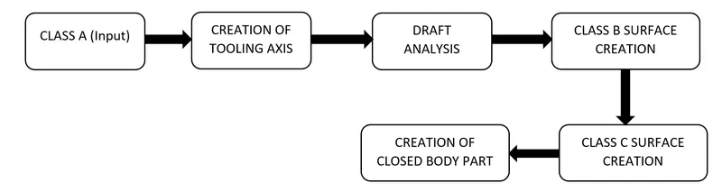
Step 1: Design Check on received Class A:
- After receiving the Class-A for the Base Bracket check for the connectivity of the surfaces on it.
- Use Join operation, boundary operation and disassemble.
- The check is over if any discontinuities do not arise.
- Delete the operations after the check.
Step 2: Determine the Tooling Axis:
- Create a Dummy Tooling axis along the best possible direction as per the Class A
- In this case we have chosen Z axis as dummy as it doesn’t interfere with any slots or holes
A) TOOLING AXIS CREATION:
- Create a point on class A surface with the aim to move the main tool for component creation.
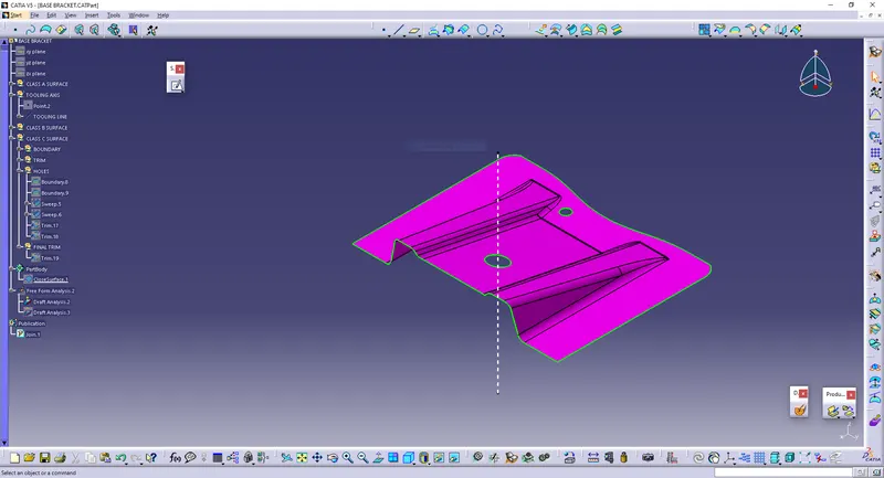
- Mask an axis over the point created with the same directions as the main axis.
- Using Intersect command from Generative Shape design select the YZ plane as the first element and the class A surface as the second element.
- After creating the intersecting lines select the Line command and join the vertices which show the most possible draft angle manufacturable and bisect those two lines over the axis point we selected at the first.
PROCUDURE for Draft Analysis of Class A Surface:
- After Tooling Axis Select the Feature Draft Analysis option from the Insert Option.
- Select the element to analyze.
- Next click on Use the compass to define the new current draft direction option and make it align with the tooling axis by dragging it to the axis.
CLASS A SURFACE:
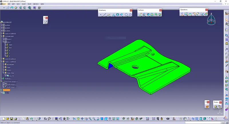
CLASS B SURFACE:
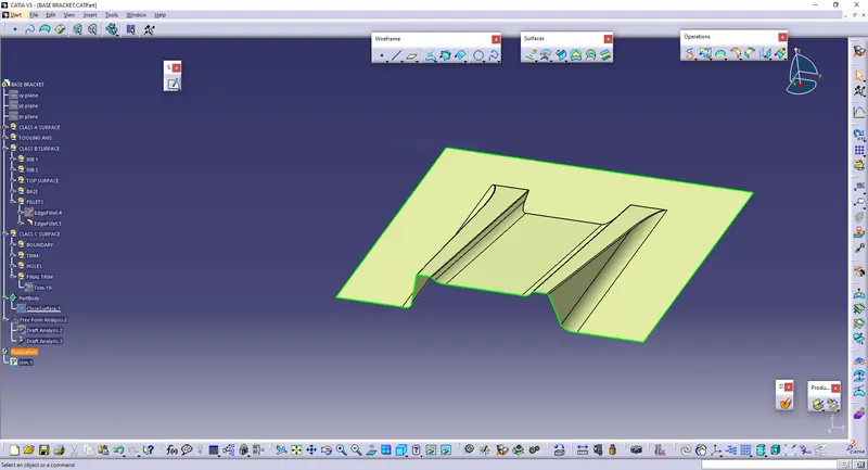
CLASS C SURFACE:
Select the boundary option and click on the boundary of the class A surface to create a sketch of the boundary.
Using sweep command select with draft direction option and set a 3-degree draft to create a sweep of the boundary in Z-axis with angle.
Select the appropriate direction to get the draft.
Similarly, create the boundaries for the two holes and sweep it with 3degrees to the draft angle.
Join all the elements.
SOLID COMPONENT:
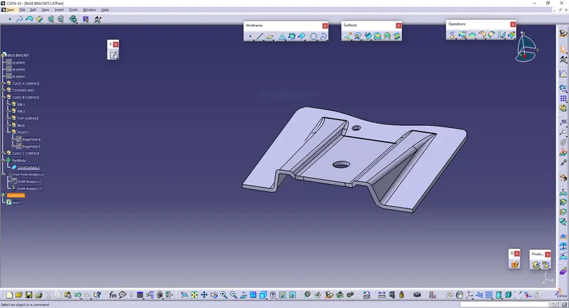
DRAFT ANALYSIS of the SOLID part:
- Select the element to analyze.
- Next click on Use the compass to define the new current draft direction option and make it align with the tooling axis by dragging it to the axis
CONCLUSION:
Created a Base Bracket Plastic component through the given Class-A surface and draft analyzed the surface with 2.6 degree of draft angle.