Week 8 - Challenge 1 - Base Bracket Design
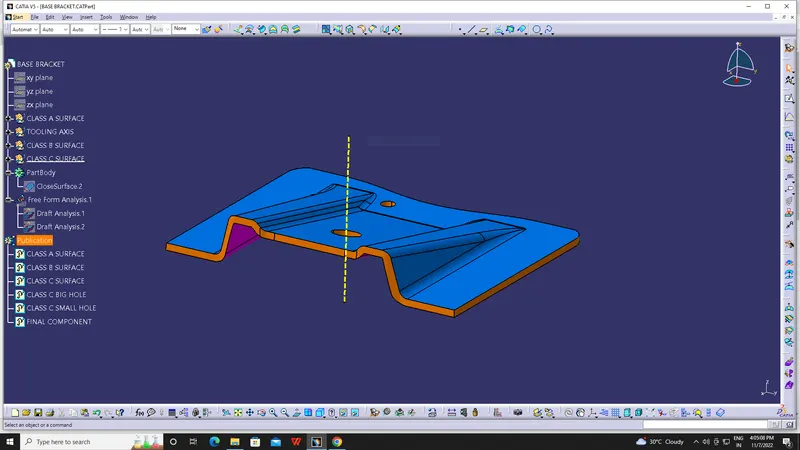
TOOLING AXIS
Tooling Axis is the direction in which the Mold opens and closes.The tooling axis is the flow of molten material into the mold.
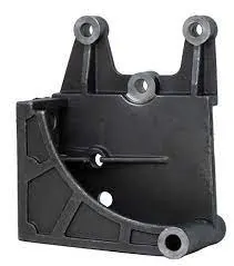
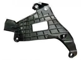
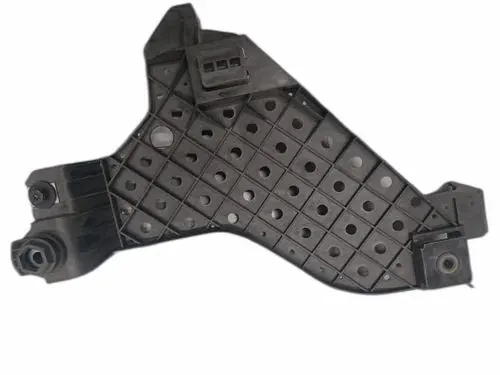
ABOUT BASE BRACKET
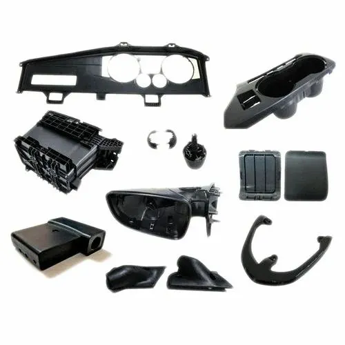
A Bracket is a component used to support load or any attachments to structural element for heavy. vehicle. It is subjected to different types of loading while the vehicle is in motion. One of the main common. loading is static load which is assumed to be constant throughout the operation.(It is used in the bonnet of car,The base bracket are used to hold the links of holding the hood)
MATERIAL SELECTION OF BASE BRACKET
Polypropylene
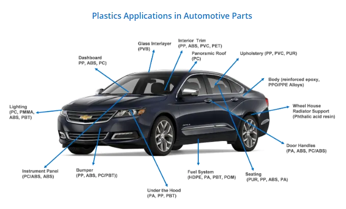
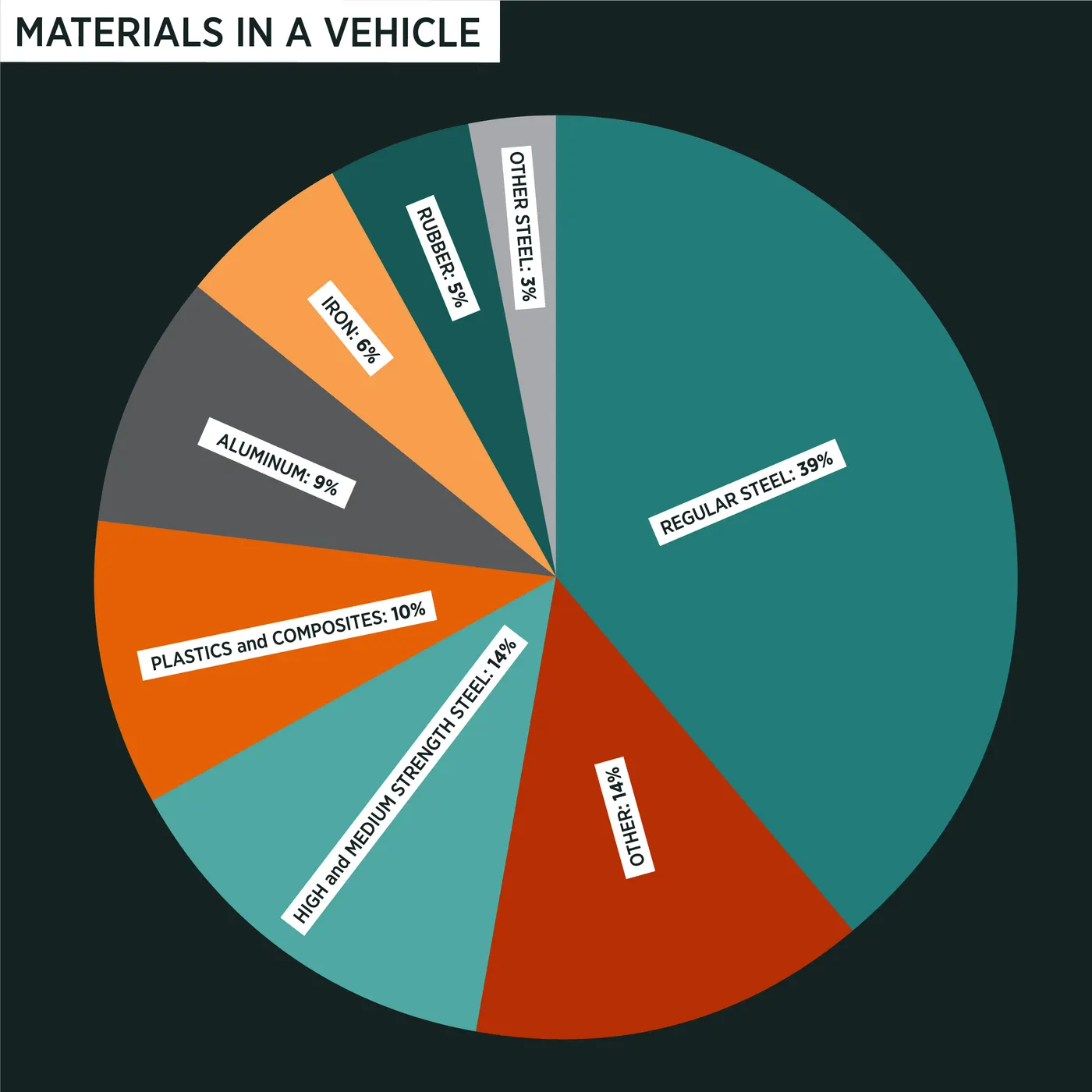
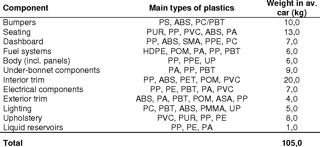
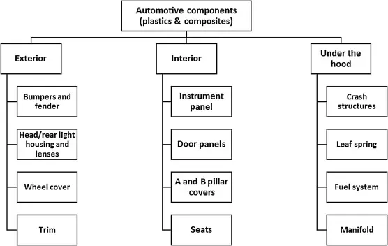
Polypropylene is used the most frequently of any plastic in automotive manufacturing. Being a thermoplastic polymer, it can easily be formed into almost any shape. It has excellent chemical and heat resistance and is generally resistant to impact. Given this plastic's resume, you will frequently find it in car bumpers, gas cans and even the carpet fibers of your car's interior flooring. It's also a more economical alternative to expensive plastics of similar strength and durability, which helps drive down the cost of manufacturing.
- polypropylene,
- polyethylene,
- polyvinylchloride,
- polystyrene,
- polyethylenetheraphthalate and
- polycarbonate.
WHY THERMOPLASTIC MATERIAL
- HIGH IMPACT RESISTANCE
- REMOLDING AND RESHAPING CAPABILITIES
- CHEMICAL RESISTANT
- AESTHETICALLY SUOERIOR FINISH
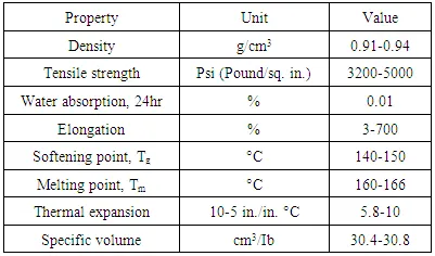
MECHANICAL PROPERTIES OF POLYPROPYLENE
ABOUT CLASS A
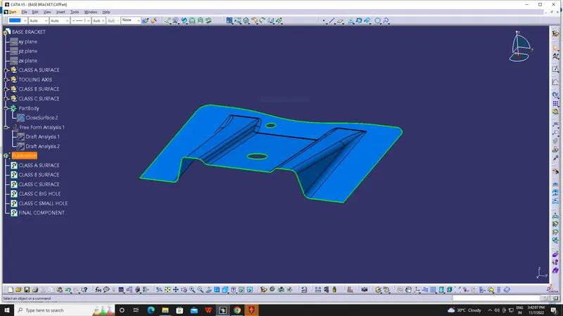
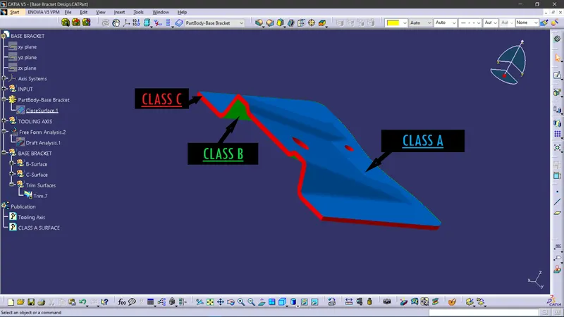
- In automotive design, a class A surface is any of a set of freeform surfaces of high efficiency and quality. It is the visible aesthetic surface of any automotive component. Class A surface refers to those surfaces which are visible and abide to the physical meaning, in a product. This classification is primarily used in the automotive and increasingly in consumer goods industry. It is a requirement where aesthetics has a significant contribution. For this reason, the exterior of automobiles is deemed Class-A.
- CLASS A is a surface which visible to customer .
CLASS B
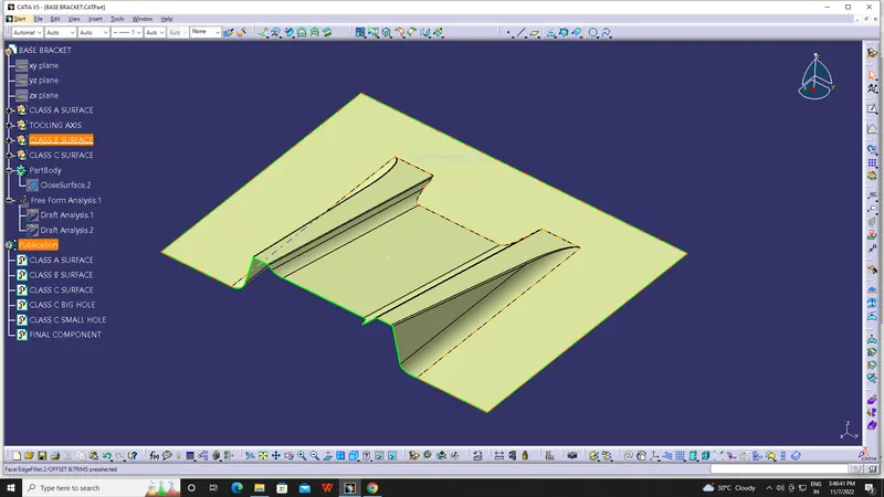
- Class B surfaces are Engineering Surfaces which are invisible to the eyes or often on the back side of the Class A surfaces. It is mainly the thickness of the component or Class A. These surfaces need to be designed as per the Class A surface i.e., the continuity, thickness of the component, functionality etc should be maintained. These surfaces include the main engineering features such as Screw bosses, Ribs, Snaps, Stiffeners and fixations. B surfaces also do not contain any aesthetic styling content and textures since it is not visible to eyes.
- offset of class A
Class- C
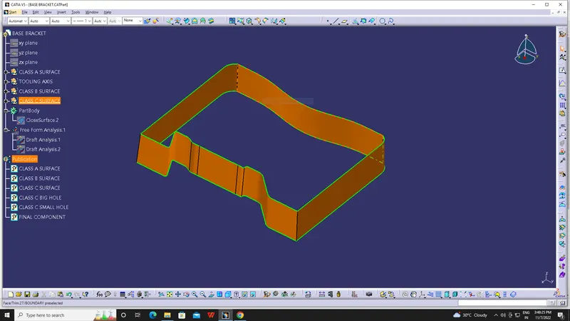
Class C surfaces are connectors between Class A and B surfaces. This surface connects both A and B surfaces along the Tooling Axis. It contains the draft as per the design. Its is basically the thickened surface between both A and B surface.
DRAFT ANALYSIS
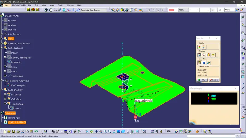
- Change View Mode Customization to Material mode
- Go to INSERT ---> ANALYSIS ---> FEATURE DRAFT ANALYSIS and move the compass to the Tooling Axis.
- Change the range to 3º.
- Apply the settings as Shown in Figure
- As shown the target area has 15º draft angle which was the concerned face.
- Thus, it passes the criteria of having suitable draft and the Class A can be further designed into plastic component and manufactured.
DRAFT
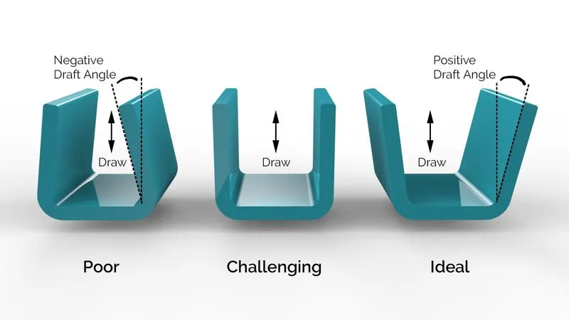
- Draft is an angular tapering given at the design stage to every Plastic Component that has to be manufactured. It is given in the direction of the Mold Movement. The Draft allows the parts to release easily from the mold without creating friction between the surface of component and the core and cavity plates.
- When a Plastic component cools down inside the mold, the natural tendency of it is to shrink and attach to the core or cavity half. The movement of mold opening causes friction on the walls of the component as well as the core/cavity blocks. This reduces the life of the mold as well as the component itself. The component may also have rough surface finish as well as weak structure due to this. This problem can be solved by giving draft to the component.
- Most applications require minimum draft angles of around 0.5º to 1º , however 3º draft angles are widely accepted for cost saving purpose. 7º Draft angles are given to textured surfaces like Instrument Panels. Minimum possible draft angles are given to screw bosses, ribs and stiffeners due to their critical nature.
PROCEDURE TO FOLLOW THE BASE BRACKET DESIGN

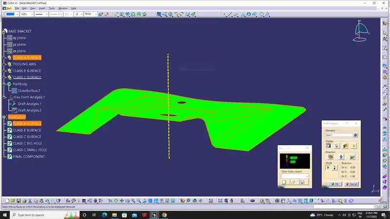
DRAFT ANALYSIS OF CLASS A
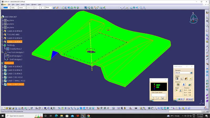
DRAFT ANLYSIS OF FINAL COMPONENT
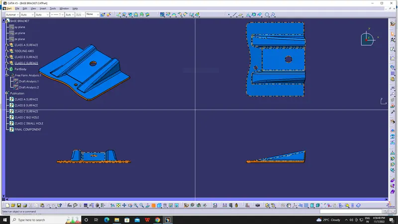
SCREEN SHOT OF TREE STRUCTURE
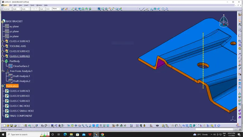
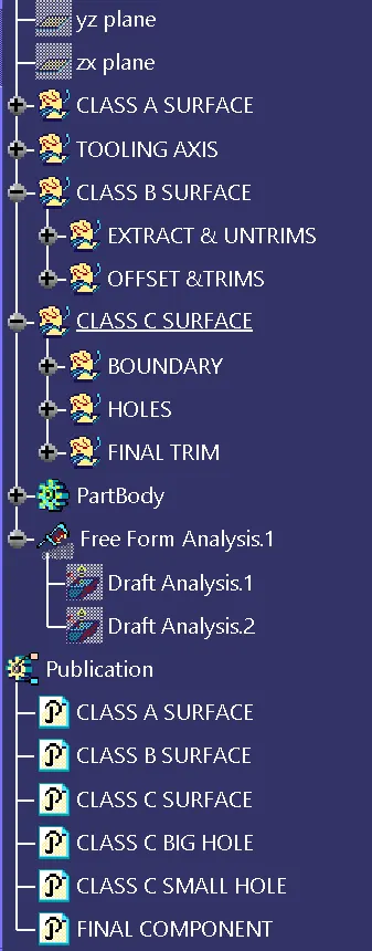
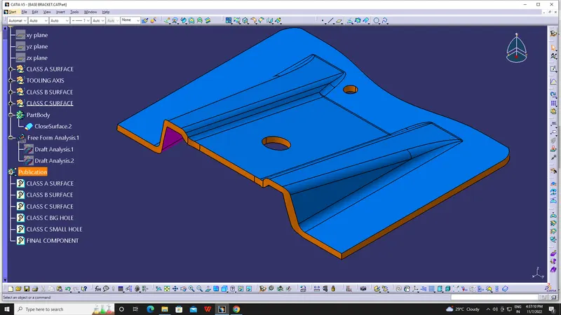
SOLID MODEL OF BASE BRACKET WITH THE PROPER COLOUR CODE OF CLASS A,B&C