Week 8 - Challenge 1 - Base Bracket Design
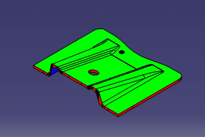
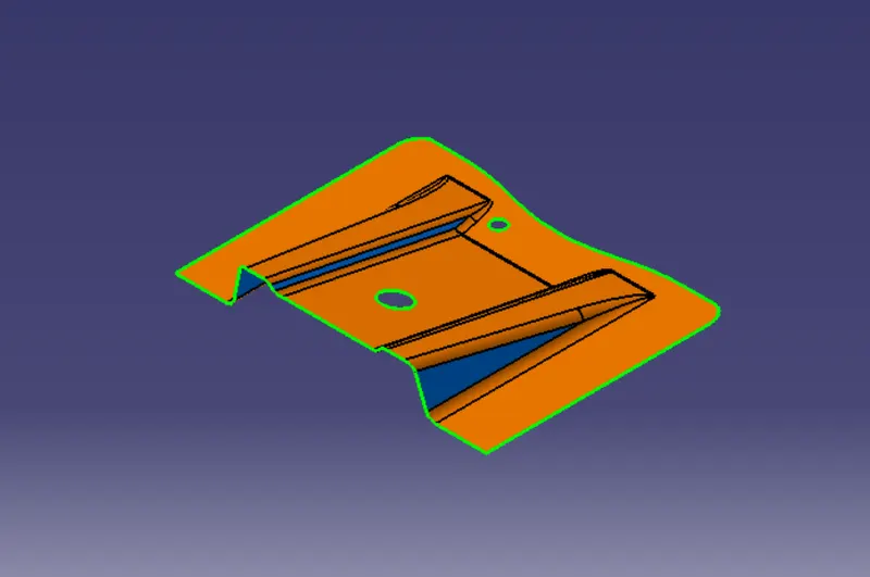
GIVEN CLASS A SURFACE
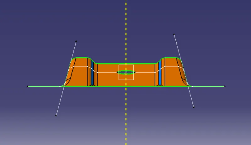
By using Bisecting line command to create a Tooling axis
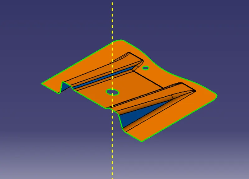
FINAL TOOLING AXIS
BASE BRACKET DESIGN PROCEDURE
CLASS-B SURFACE
RIB CREATION
- Bringing in the class-A surface.
- Extracting the rib surface.
- Un-trim the extracted surface.
- Extrapolate the un-trimmed surface.
- Trim the surface as per the required shape.
- Repeat steps 2, 3, and 4 for the next rib surface.
- Offset the created rib surfaces for 2.5mm. ( CLASS-B SURFACE)
MIDDLE FLAT RIBS CONNECTING SURFACE
- Extract the middle flat connecting surface from class-A.
- Un-trim the extracted surface.
- Extrapolate the un-trimmed surface.
- Offset the extrapolated untrimmed surface for 2.5mm.
- Trim the surfaces. (CLASS-B SURFACE)
CREATION OF BASE SURFACE
- Extract the base surface from the class-A surface.
- Un-trim the base surface.
- Extrapolate the base surface.
- Offset the base surface for 2.5mm
- Trim the base surface from the middle surface which is already created.
JOIN
Join all the class-B surfaces to make them as one unit.
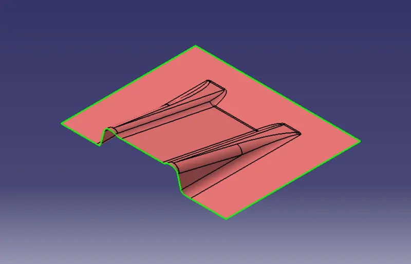
FILLET
Since the class-B surface is 2.5mm downwards to the class-A surface need to add this offset distance with the filleting radius observed from the class-A surface.
CLASS-C SURFACE
This is the connecting surface of class-A and class-B surfaces.
- Create the boundary of the class-A surface using the boundary command.
- Use sweep command to generate class-C surface along the draft direction with 3 degrees drafting angle concerning the tooling axis.
- Extrapolate the hole features from the class-A surface and trim them.
FRONT VIEW
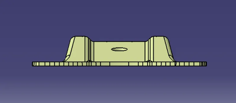
TOP VIEW
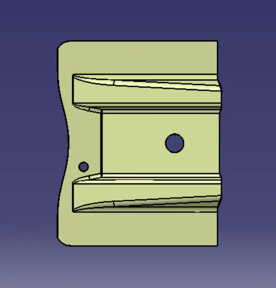
SIDE VIEW
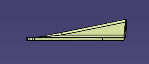
ISOMETRIC VIEW
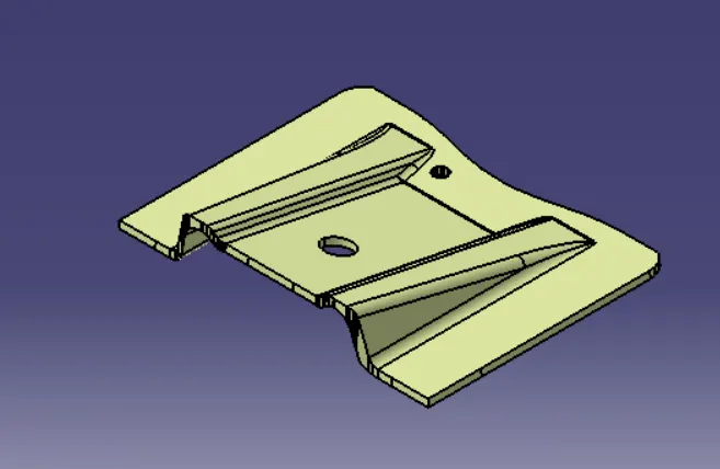
CLOSED SURFACE
- Publish class-A, class-B, and class-C surfaces and tooling axis.
- Join all the surfaces together.
- Create a closed surface.
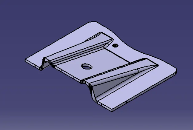
DRAFT ANALYSIS-3 DEGREE
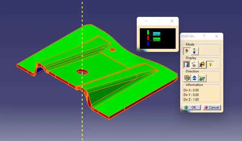
FINAL DRAFT ANALYSIS