Week 8 - Challenge 1 - Base Bracket Design
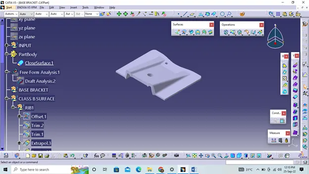
STEP 1: Check the Class A surface connection
Use the join statement to make sure there is no gap between the component.
We can check this visually or by clicking on the border command.
It has 3 boundaries, one outer and two inner boundaries of the circle.
Therefore, the first check is complete.
Tooling Axis:-
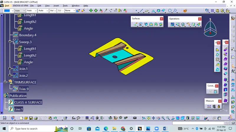
Visually check which tool axis is best.
Check the axes.
z is the best possible tool axis.
Creating a tool axis along z:
Therefore, the main axis of the tool is along the z-axis.
Now analyze the design using the Analyze Selected Design tool in Tools.
Bisecting method:-
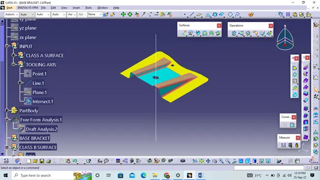
The bisect method is basically used to find the correct tool axis using a dummy tool axis. The bisect method uses a bisector that either bisects the two lines, or an error is displayed, indicating that the two lines are parallel to each other. To know if a given surface is machinable or not, we intersect the surface with the corresponding plane and get a sketch that consists of two lines and using the bisect line option, we bisect the line that creates a line in the middle of those two lines. Likewise, we will create a tool sweep axis for x and y, which will be used to create the main tool axis using the bisect line option in the line command.
Draft Analysis:-
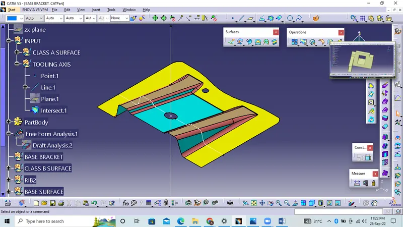
The pull allows the part to be released from the mold, most parts or applications require a bevel angle of at least 0.5 to 1 degree, and a bevel angle of 3 d is widely used as a standard.
Before proceeding to bevel analysis, change the material mode to fit mode.
Insert - analysis - design feature analysis
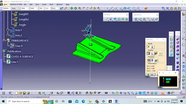
Defining the Bevel Direction Select Bevel Analysis from the toolbar and click the crosshair symbol and drag the crosshair from the top right corner of the workspace and place it on the component where you want to perform the bevel analysis. The "W" of the compass and the axis of the tool should be aligned on the same line.
By clicking on the surface and using the flip tool, we can assign a flip direction.
Click on the lock symbol and click on the component, then a draft value table will appear.
Analyzing below the waypoint and moving the mouse over the surface will display the details of the surface directly.
Class B surface:-
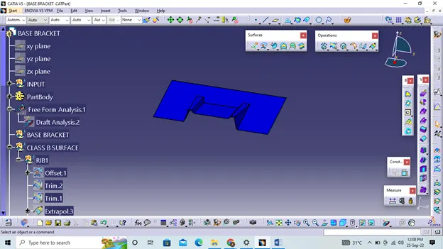
Initial extraction of the right side rib using the Class A surface extraction option.
Then Extrapolate to increase the length
Now trim the surfaces to the desired surfaces
Then offset the surface to get the desired thickness
Similarly, create the left side rib
Now Similarly, get the sloped and flat surface and move it to the desired value
And now trim to get the desired surface
Now fillet the surface to the required amount
Class c surface:-
Surface C was created with reference to the boundary lines of surface class A and drag it with reference to the tool axis, then the holes are created in the same way.
Then connect the C surfaces and the holes to the A class surface.
Finally, trim the joint with surface B to get the final compent.
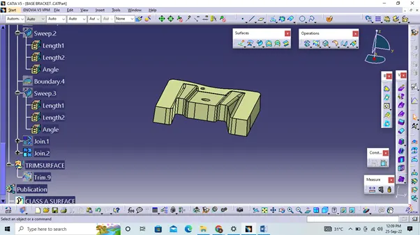
Using Final Trim Create a solid using a nearby surface on the part workbench.
Close Surface:-