Week 8 - Challenge 1 - Base Bracket Design
BASE BRACKET DESIGN
TOOLING AXIS CREATION
1. We need to check all the possibile direction of tooling axis in x,y,z axis to reduce the side core.
side core increases the tool cost
2.For this component in x direction
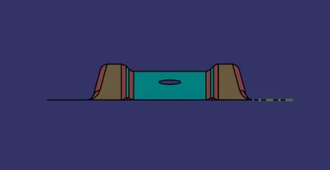
fig 1
When we considering the view as top view of tool direction (ref fig 1)
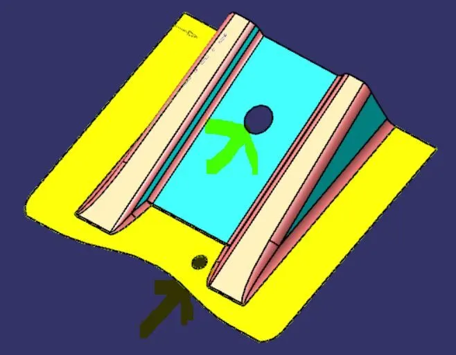
fig 2
In this direction clearing of holes is difficult.it needs 2 side core to clear(ref fig 2)
3.For this component in Y direction
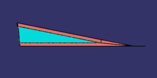
fig 3
When we considering the view as top view of tool direction (ref fig 3)
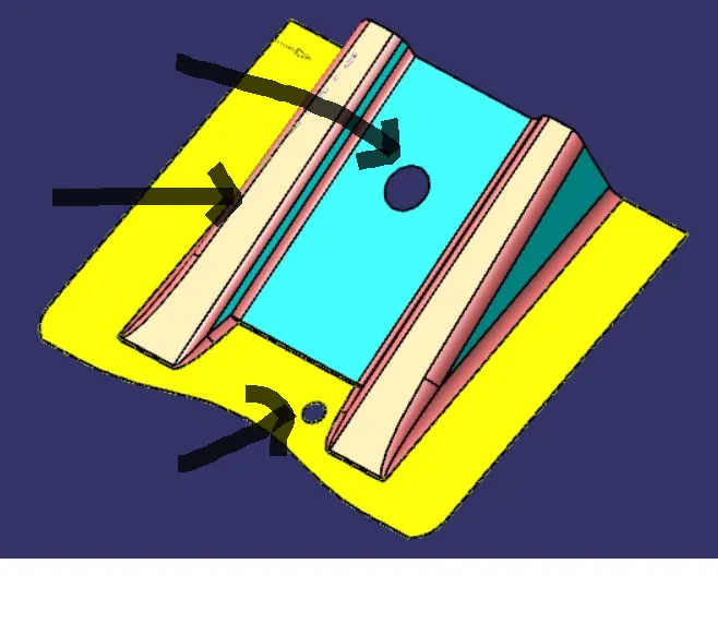
fig 4
In this direction clearing of holes and Rib is difficult.it needs 3 side core to clear
4.For this component in z direction
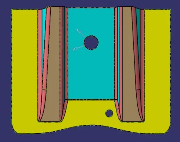
fig 5
When we considering the view as top view of tool direction (ref fig 5).In this view all face of component is visible.
so we consider this as tooling direction manually
5.we check manually by using bisecting method and then we go for draft analysis.
6. For this component at Z direction, we can take axis centre at 2 hole (small and big hole) and check,But max possibility we can check the big hole. it covers max rib area of draft.if it clears automatically small hole will get clear.if needed we can check for small hole also
7.Create a centre point on big hole and create a centre line along Z direction and name it as Dummy tooling axis
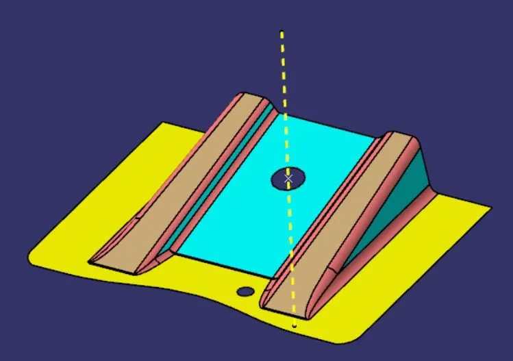
fig 6
8.To create the boundries along plane.Use intersection command, select the part and axis plane
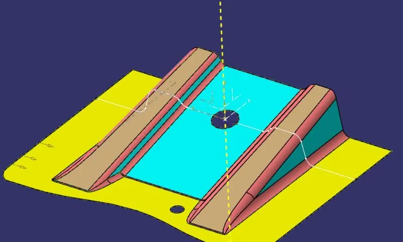
fig 7
9.Hide the dummy tooling axis line
10.Create a parrallel line along the draft angle of outer ribs
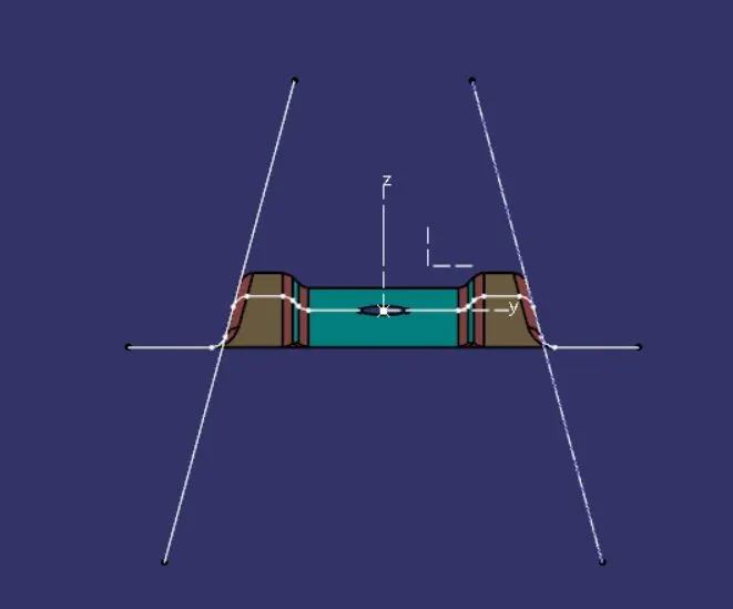
fig 8
11.create a bisecting line with reference to parrallel line drawn along the draft of outer ribs
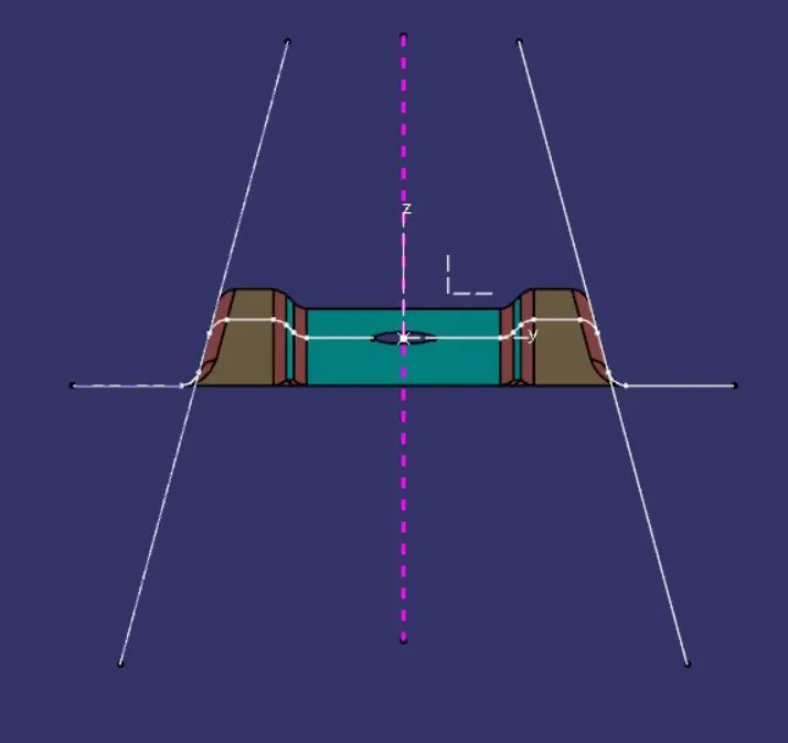
fig 9
Figure 9 represent the Main tooling axis line.By using this line we are going check with Draft analysis.
12.For Draft analysis, Click Insert -> Analysis -> Draft analysis .below dialog box will open Fig 10,11,12
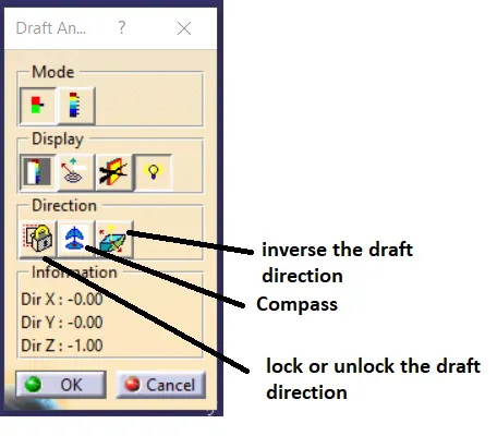
fig 10
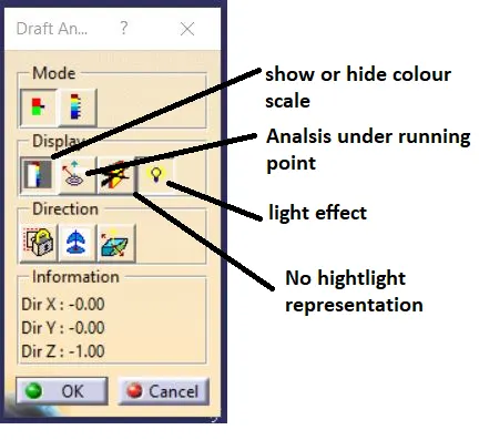
fig 11
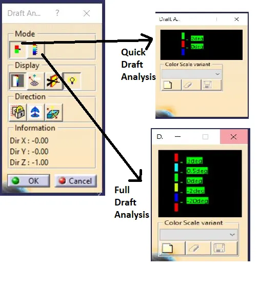
fig 12
13.First we need to fix the compass in main tooling axis using Compass command
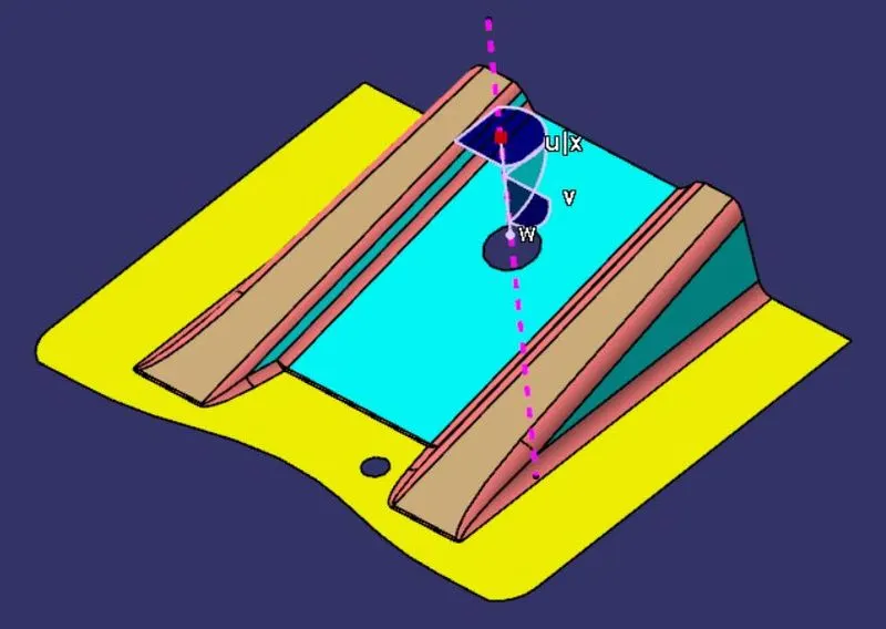
fig 13
14.Then click quick draft analysis.
In that colour varient represent the draft variation
Red-represents 0 deg
Green- represents 0 to required draft angle we are checking
blue- represents -ve draft angle .which the tooling axis cannot clear
simply move the cursor over the component,to check whether it is in inverse draft.If it shows blue colour when moving over component.Click inverse the draft direction tool bar.Then it shows green colour if it is correct valve of draft entered.
Then click lock or unlock draft direction command to lock the compass
For plastic component max draft angle is 3mm.Now we are going to check for 1,2,3 deg and max degree
1 deg-cleared- (fig 14)
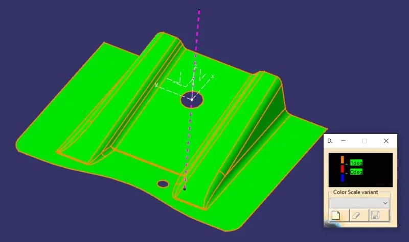
fig 14
2 deg-cleared (fig 15)
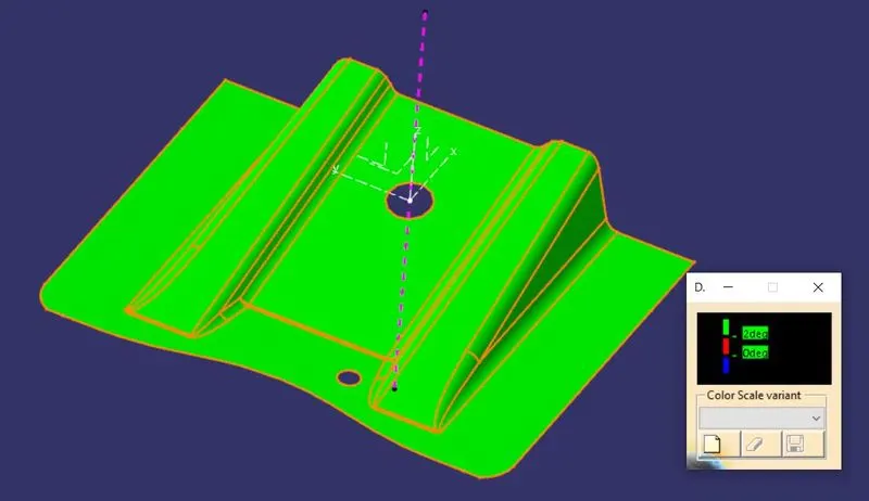
fig 15
3 deg-cleared (fig 16)
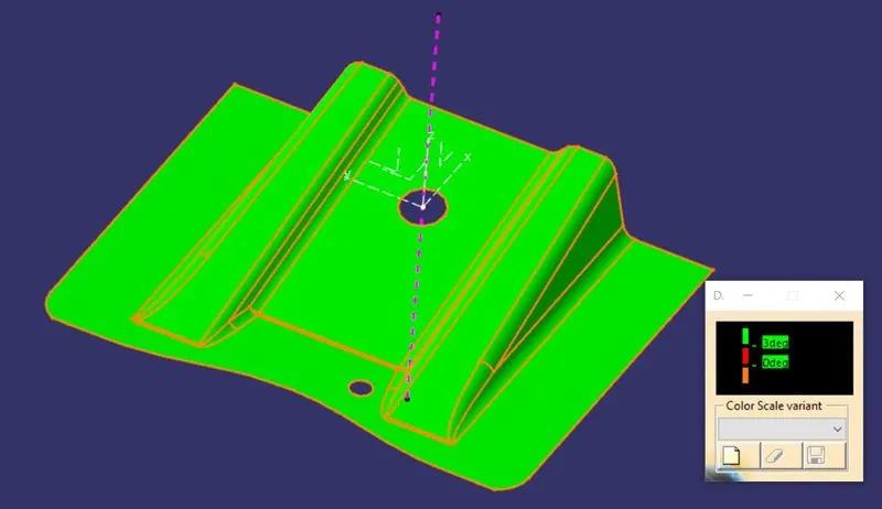
fig 16
15 deg-cleared (fig 17)
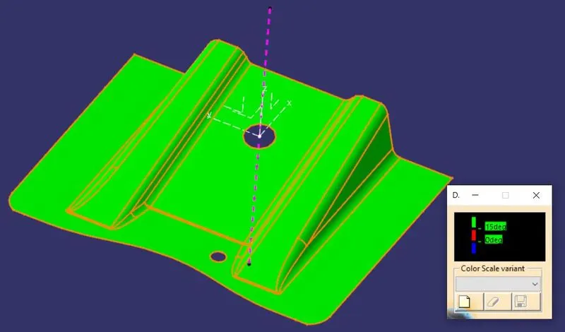
fig 17
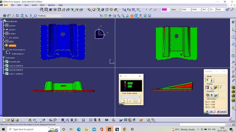
16 deg-Not cleared. In this side rig is not getting cleared.(fig 18)
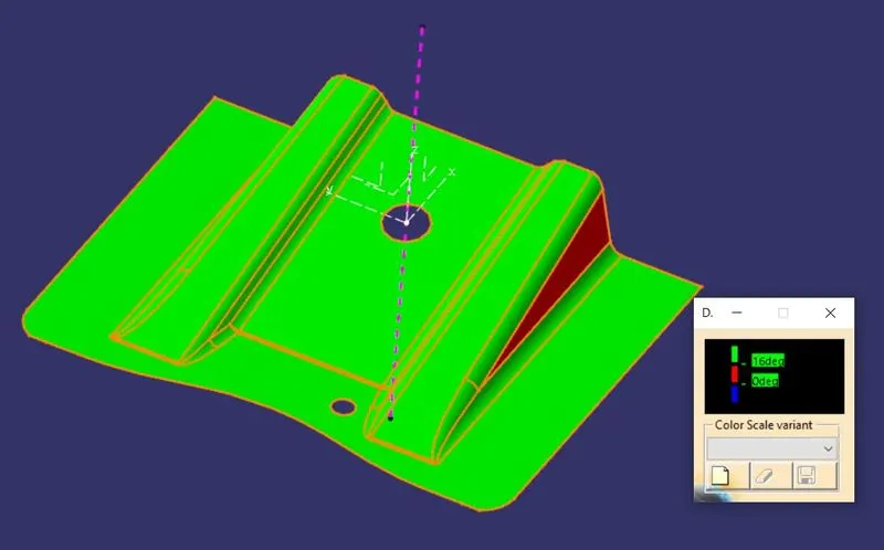
fig 18
15.There are some command like Axis along running point,we can also check the draft at specific point of our tooling axis
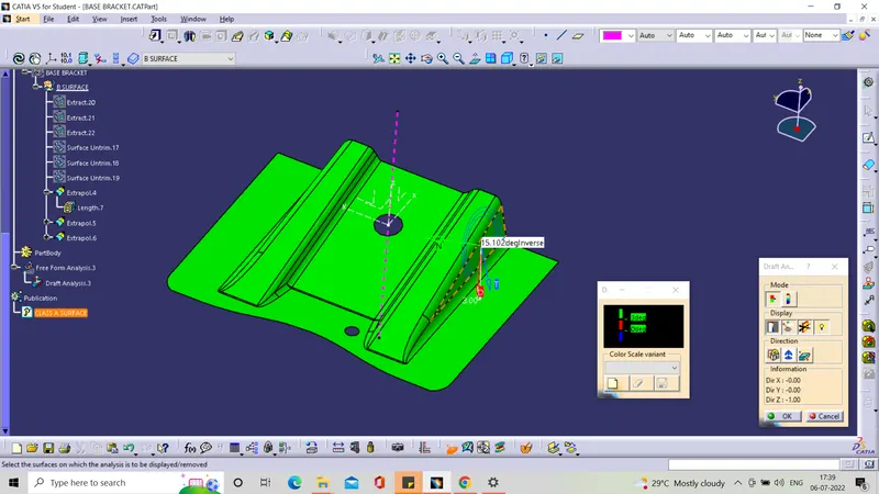
fig 19
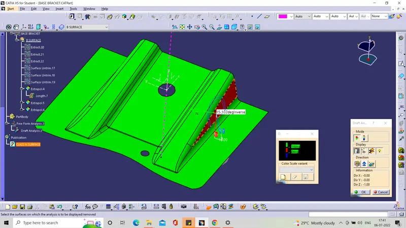
fig 20
16.By this we can conclude the draft angle at initial.After the part is created also we need to do below step
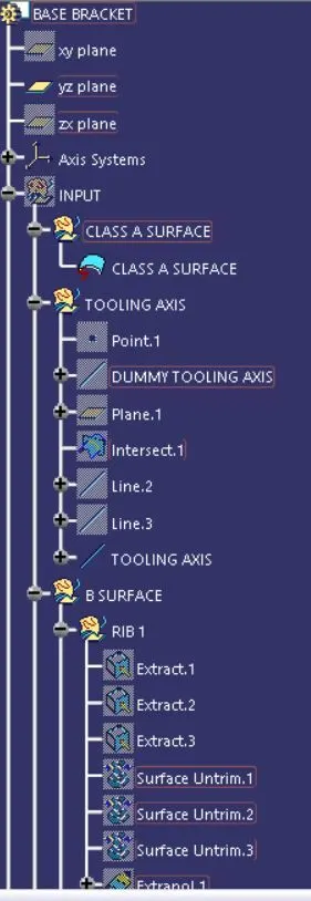
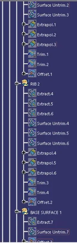
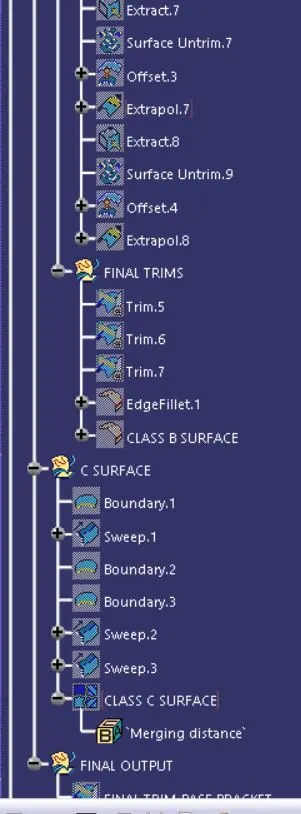
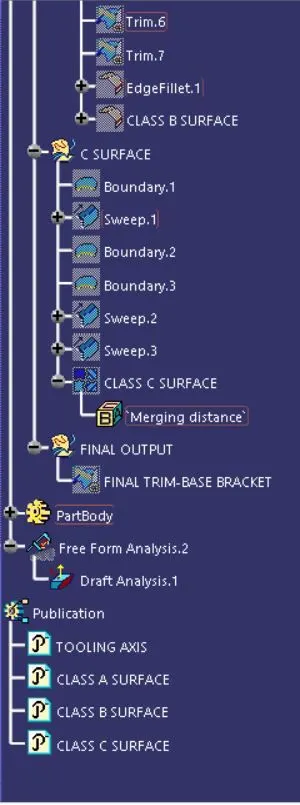
17.Create surface B
16.Create surface C
17.Merge both Surface B and C,It is final outcome of surface
18.By using the go to part design and make the closed solid part
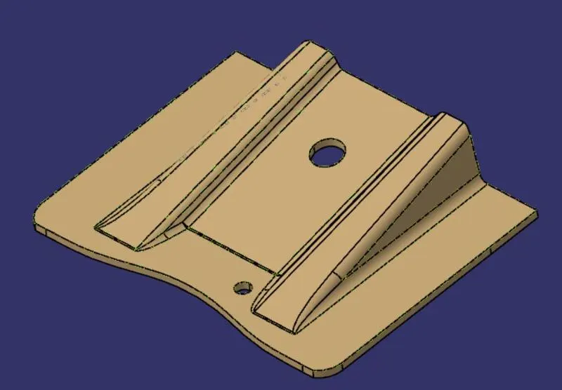
fig 21
19.Again go to draft analysis and Check with final draft angle created, i.e 2,3,15,16 Deg as checked above
2deg
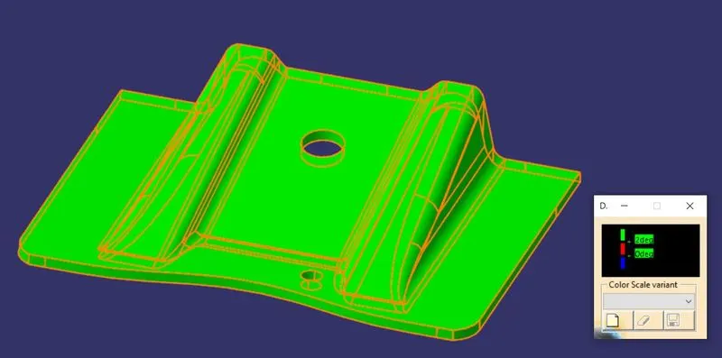
fig 22
3deg
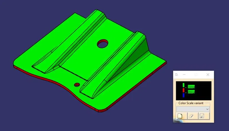
fig 23
15 deg
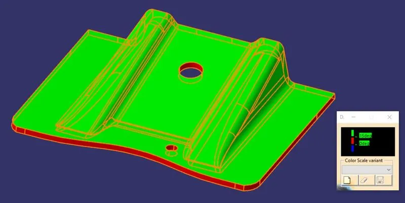
fig 24
16 deg
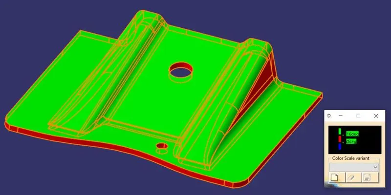
fig 25
From the above figures 21 to 24.Draft angle was Ok between 2deg to 3deg
Conclusion
we have finalized 3degree will be maximum draft for this component
Views
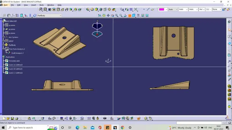
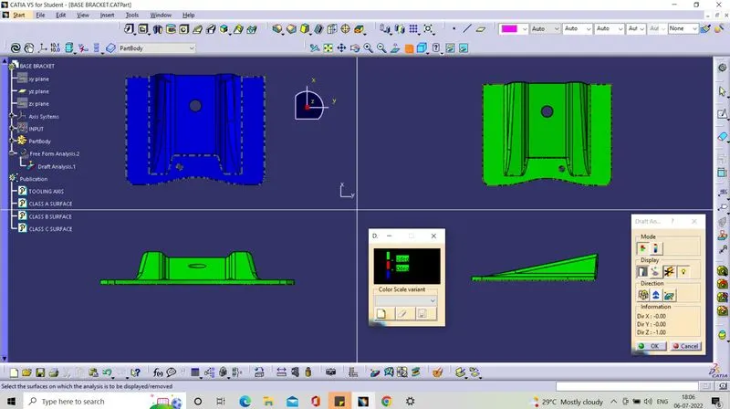 2 deg
2 deg
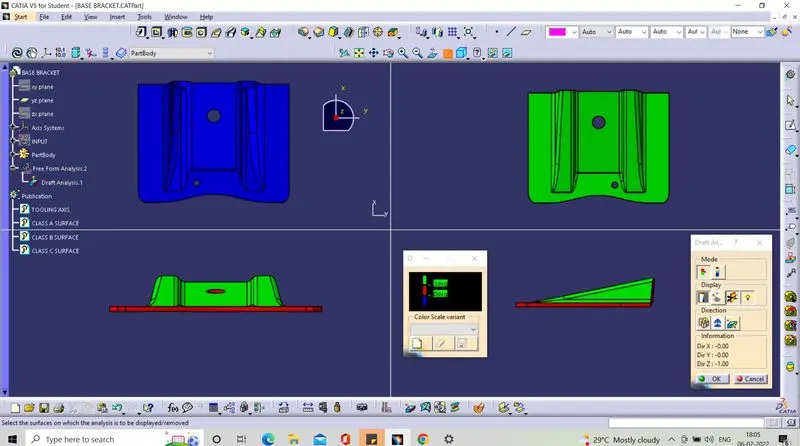 3 deg
3 deg
 16 deg
Geometric sets