Week 8 - Challenge 1 - Base Bracket Design
Question:
Create the Base Bracket Plastic component through the given Class-A surface. To begin with, the tooling axis for the given Class-A Surface should be created meeting the requirements of the draft angle and at the end perform the Draft analysis on the model.
Solution:
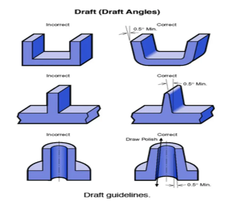
Procedure for designing Base bracket:
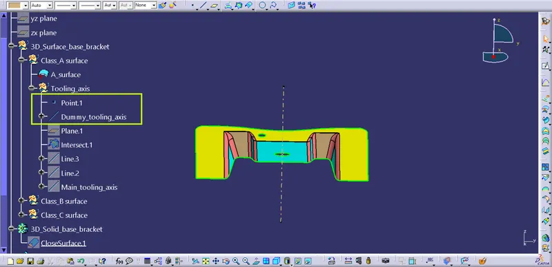
Fig1.1: Provided Class_A surface and created 'Dummy tooling axis' in Z-direction to clear the holes.
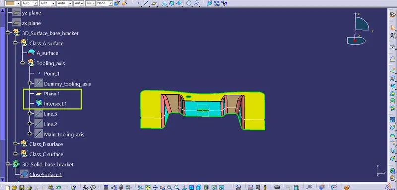
Fig1.2: Creating intersection profile by using plane and class_A surface.
We don't have any objectionable curves and surfaces in X-direction but we do have some surfaces inclined at an angle to Y-axis. Therefore checking the Y-direction for Tooling axis.
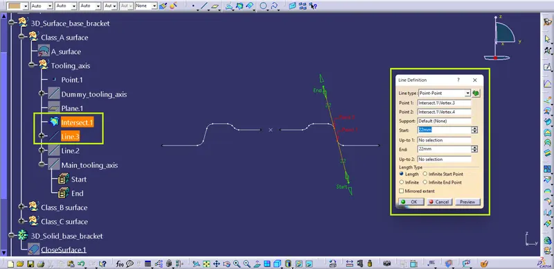
Fig1.3: Creating line-01 at angle of same as that of objecnable surface-01.
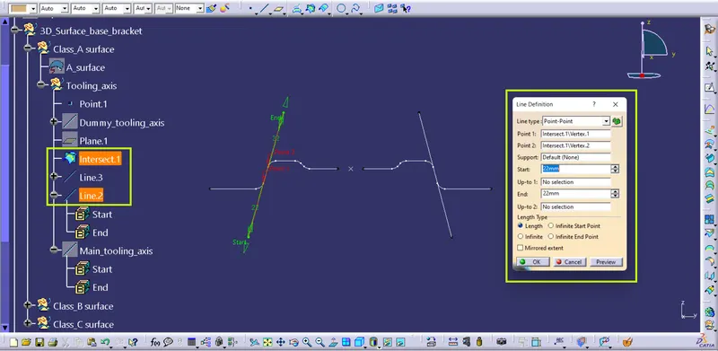
Fig1.4: Creating line-02 at angle of same as that of objecnable surface-02.
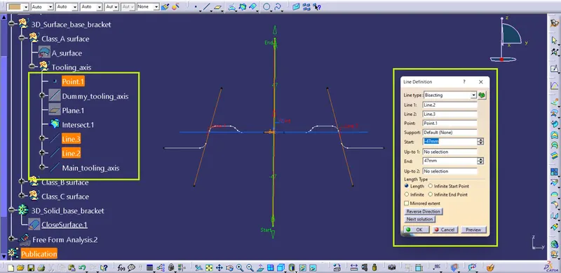
Fig1.5: Creating bisecting line at mid-point, bisecting line-01 and line-02.
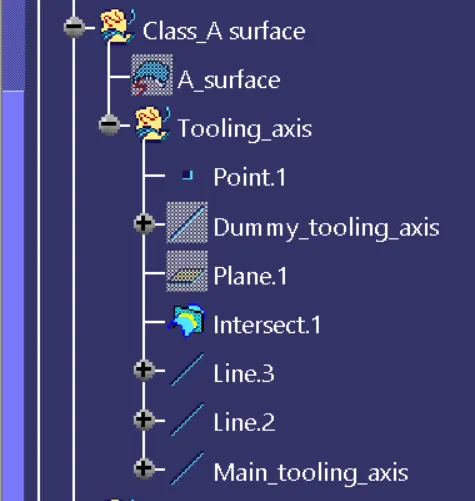
Fig1.6: Expanded tree-structure for 'Tooling_axis'.
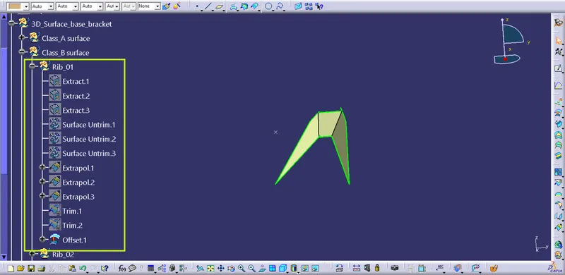
Fig1.7: Creating Rib_01 at offset of 2.5 units and expanded tree-structure for 'Rib_01'.
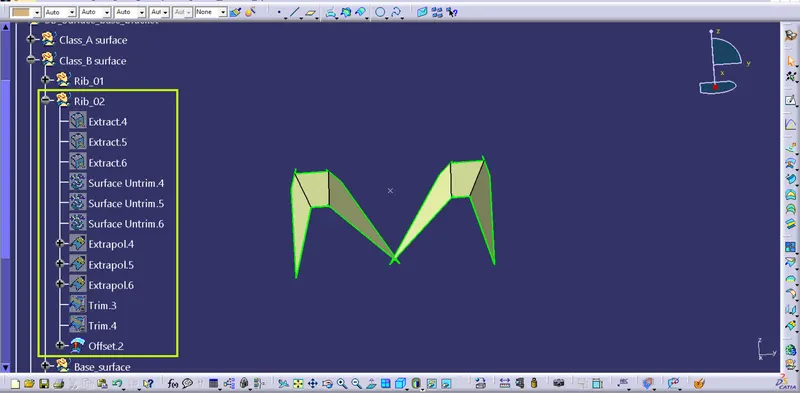
Fig1.8: Creating Rib_02 at offset of 2.5 units and expanded tree-structure for 'Rib_02'..
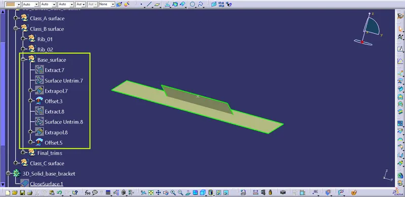
Fig1.9: Creating Base surfaces at offset of 2.5 units and expanded tree-structure for 'Base_surface'.
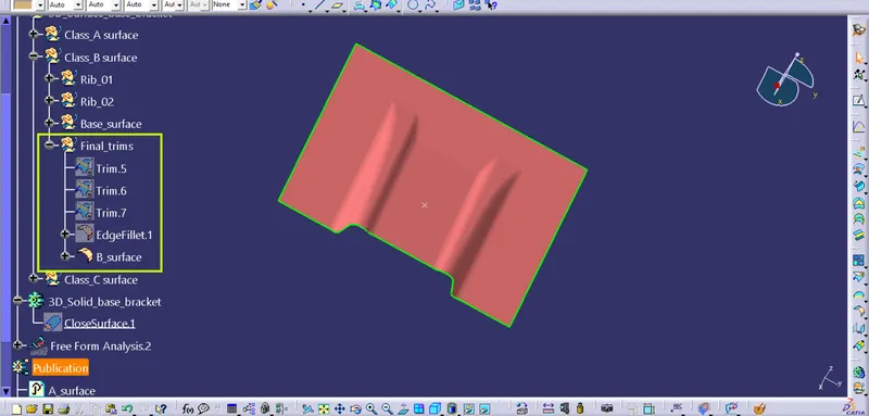
Fig1.10: Creating Surface_B at offset of 2.5 units and expanded tree-structure for 'Surface_B'.
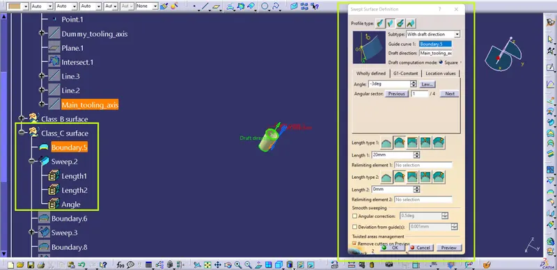
Fig1.11: Executing Swept command for hole-01 profile as a boundary.
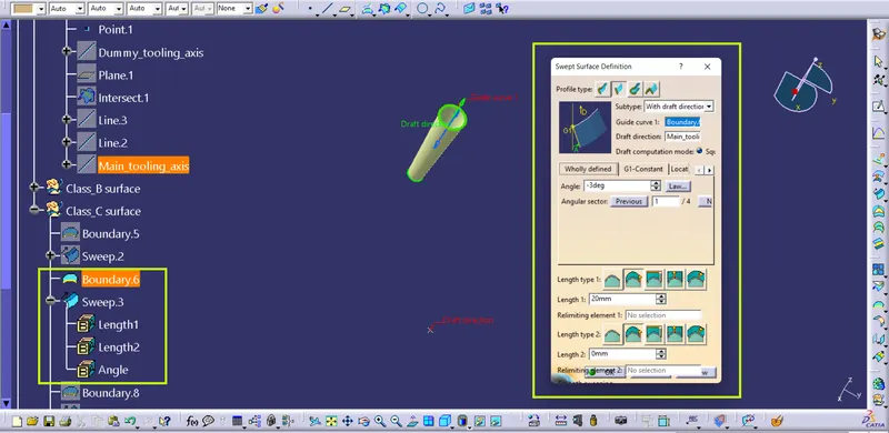
Fig1.12: Executing Swept command for hole-02 profile as a boundary.
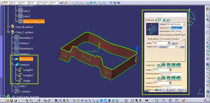
Fig1.13: Executing Swept command for Class_A surface's profile as a boundary.
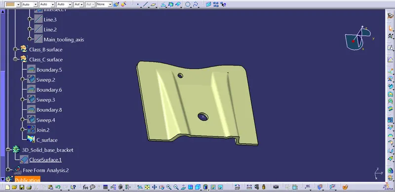
Fig1.14: Class_C surface obtained after executing the final trim operations and expanded tree-structure for the same.
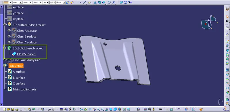
Fig1.15: Creation of 'Solid_base_bracket' by using the 'Closed_surface_feature' of the 'Part_workbench'.
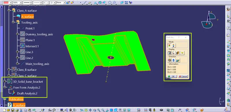
Fig1.16: Draft analysis results performed on the Class_A surface.
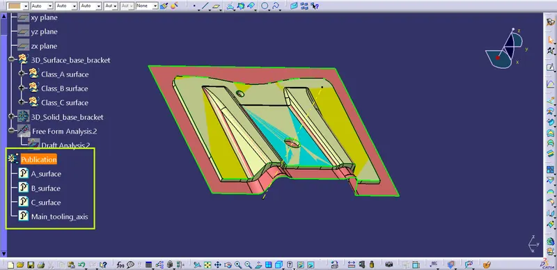
Fig1.17: Publication of Class_A, Class_B, Class_C and Tooling_axis.
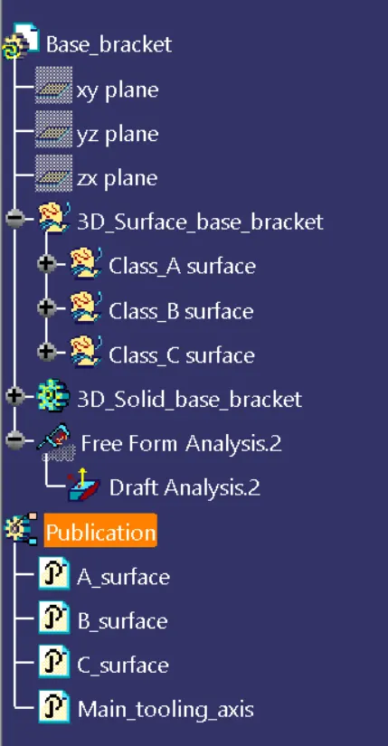
Fig1.18: Expanded tree-structure of the 3D Base bracket.