Week 8 - Challenge 1 - Base Bracket Design
Base Bracket Design
Aim
Create the Base Bracket Plastic component through the given Class-A surface. To begin with, the tooling axis for the given Class-A Surface should be created meeting the requirements of the draft angle and at the end perform the Draft analysis on the model.
Objective
To Design a base bracket in CATIA V5 using the given Class A surface and design parameters.
Input Data
We use class-A- surface as an input data
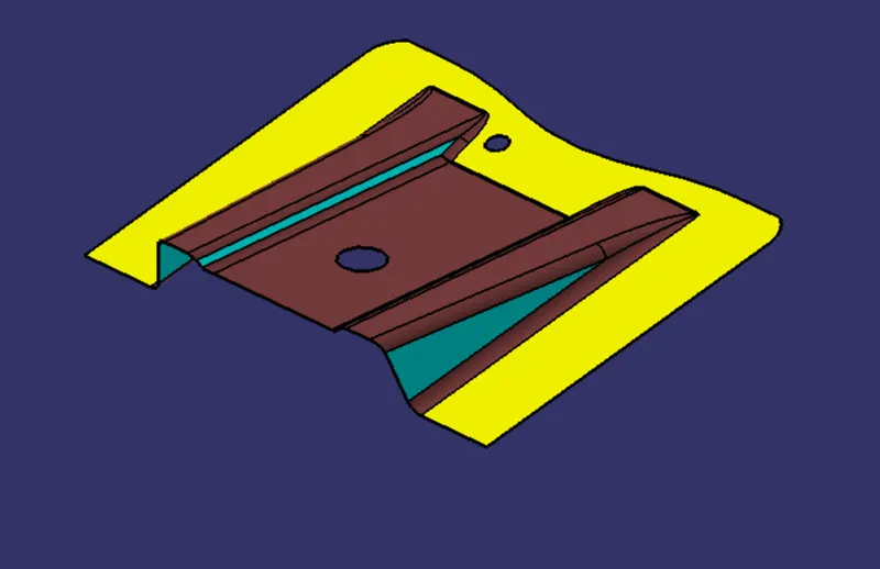
Tooling direction
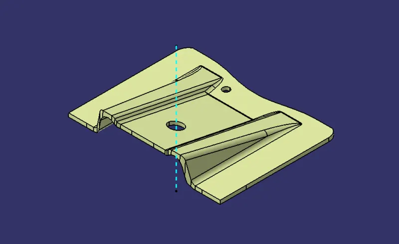
Tooling direction in which 2 halves of the mold get separated against each other. There are a lot of methods available to create a tooling direction, in this case, am going to use the bisecting method.
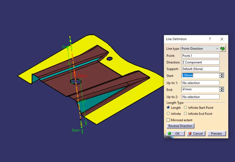
First, we need to create a dummy tooling axis in the Z direction because there is no possibility to create our part in the X and Y direction
Now create one plane on the dummy tooling axis by selecting the parallel through point. after creating the plane,create one intersection curve through the plane which we have created.
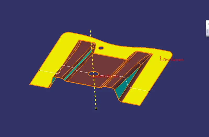
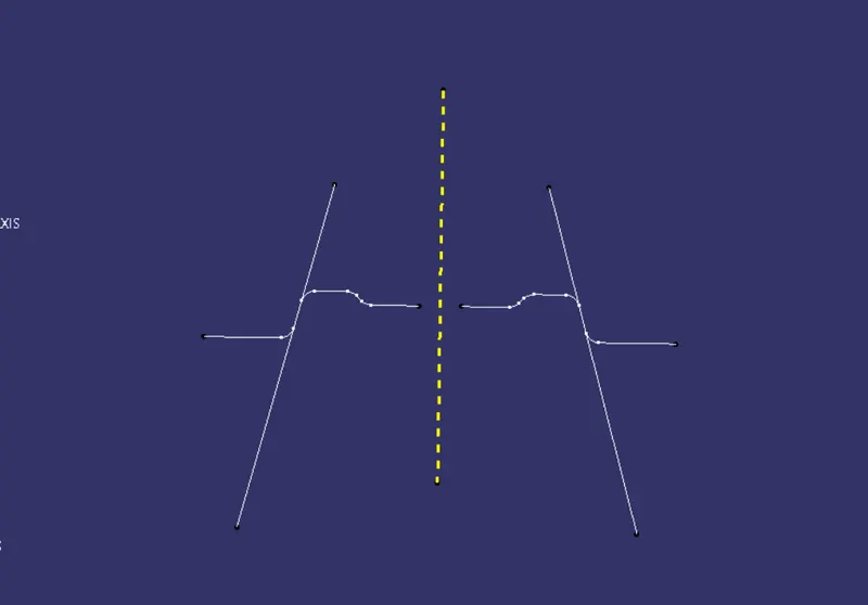
normally we are using bisecting method if our part was symmetry otherwise it is hard to create the tooling direction in this method, after the intersection curve process create lines on both sides of the intersection curve which is parallel to the dummy tooling axis then create the main tooling axis by using bisecting line command.
B surface creation
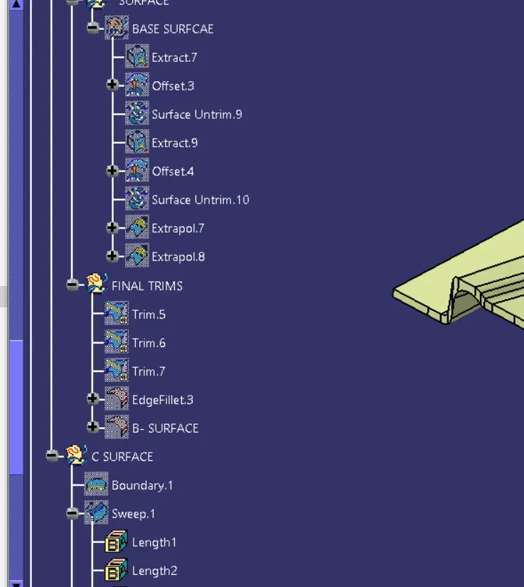
As usual B surface is created using the standard procedure by extract, un trim, extrapolate and offset commands. The B-surface is created parallel to the A-surface.
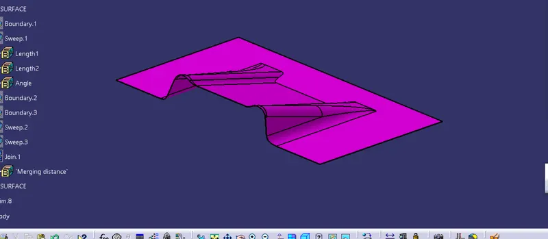
C-surafce creation
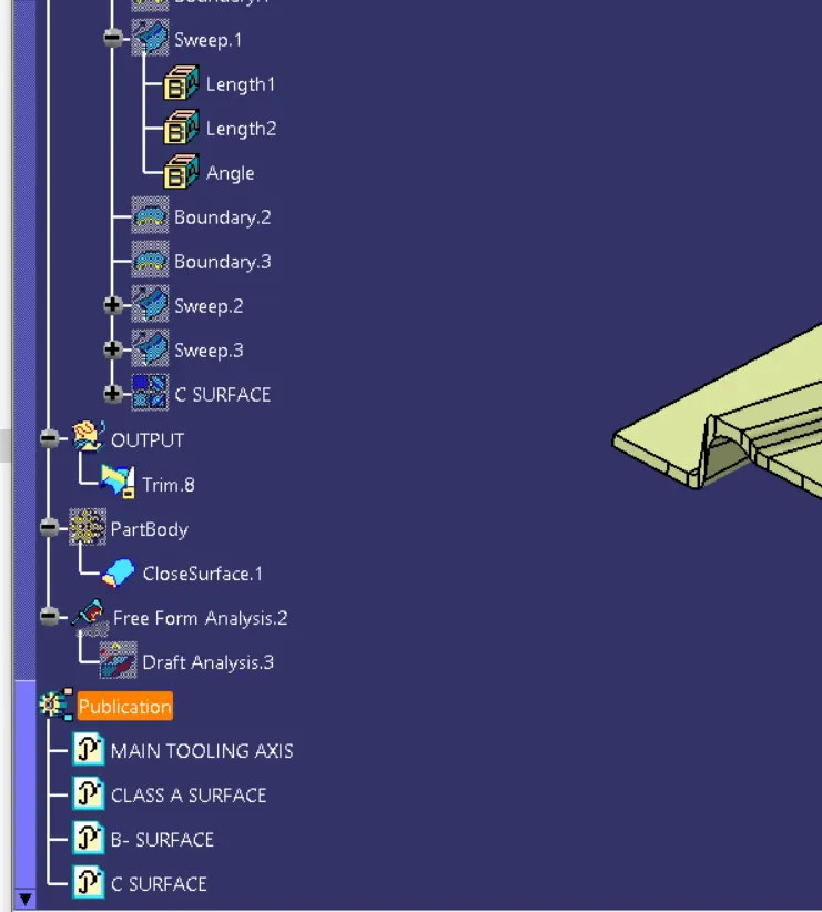
Class C surface for this component is created using sweep command. All the ends of component surface was facing downwards, so the C surface will created perpendicular to B surface.
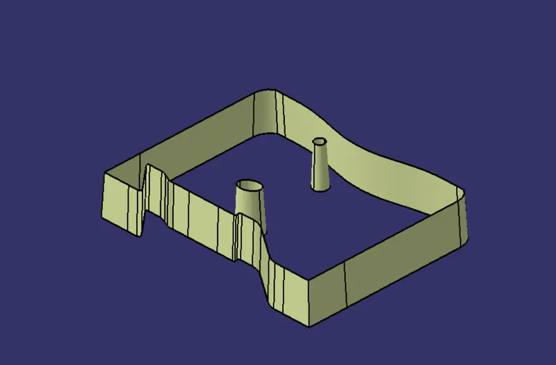
Feature tree structure
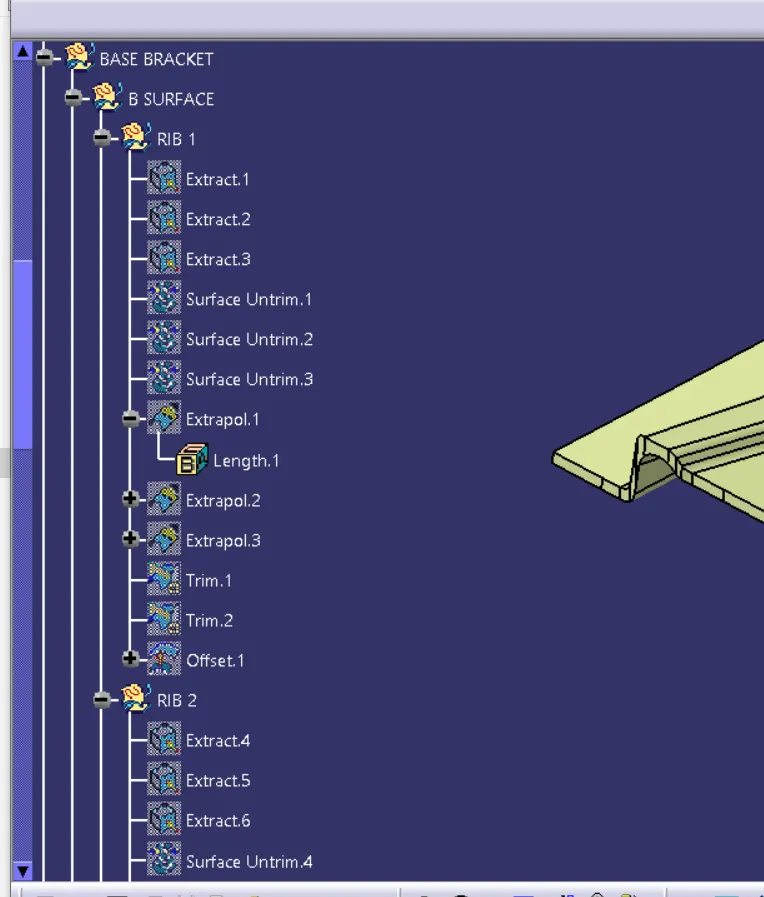
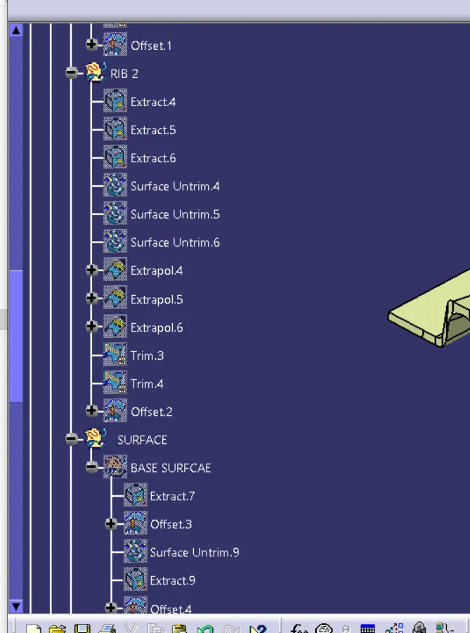
Different views
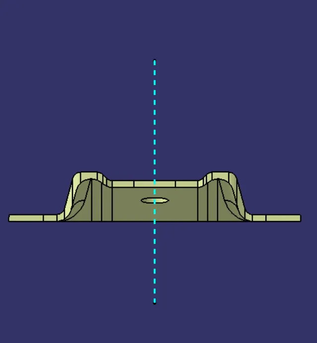
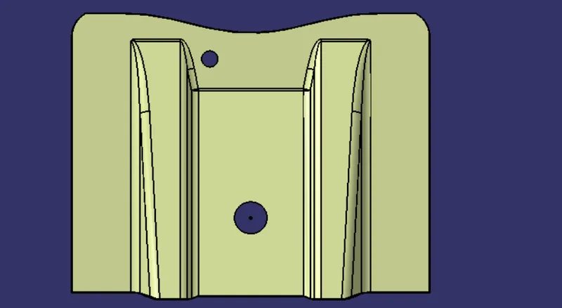
Front view
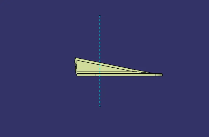
Right view
Top view
Isometric view
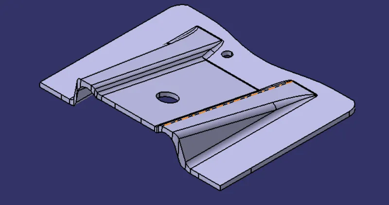
converting into a solid body
Once all surfaces are created Class A, B, and C surfaces are joined together to get the final closed volume. The closed volume is then converted into a solid body using the closed volume command in the part design workbench.
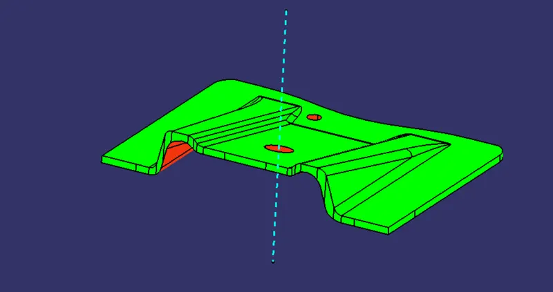
Draft analysis
The Draft Analysis allows the user to easily analyze a part for a proper draft angle and check to the manufacturability of the component
Conclusion
I have successfully completed the base bracket challenge by using CATIA V5