Week 8 - Challenge 1 - Base Bracket Design
TASK: To create a Base Bracket Plastic component through the given Class-A surface.
Steps:
- download and open the class A surface given in the STEP file
- visualize the perfect tooling direction considering (x,y,z direction)
- create a tooling axis
- create class B surface
- create class C surface
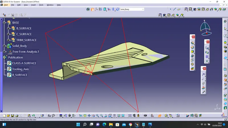
- create a solid body
Visualizing the perfect tooling direction considering (x,y,z direction)
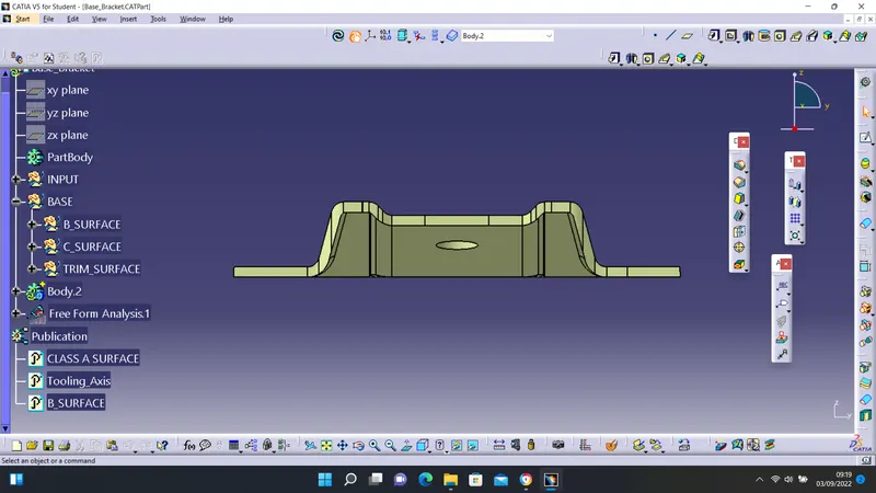
y-direction: this axis is only showing one section of the class A surface of the base bracket, this is NOT suitable.
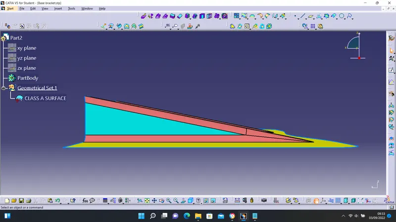
x-direction: this would have been suitable, however, there is a hole that is not clearing. Creating a tooling axis will not be cost-effective as a different tooling axis will need to be created to form the hole. Hence, NOT suitable.
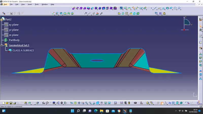
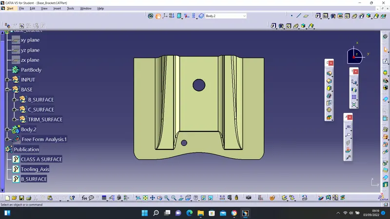
z-direction: this direction seems to be the perfect direction to create a tooling axis. All the sides and edges of the class A surface are clear and visible. In respect of this, a tooling axis WILL be created in the z-direction.
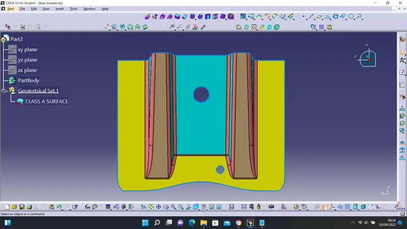
CREATING TOOLING AXIS
- create a dummy tooling axis at the z-direction
- create intersection lines in the z and y direction
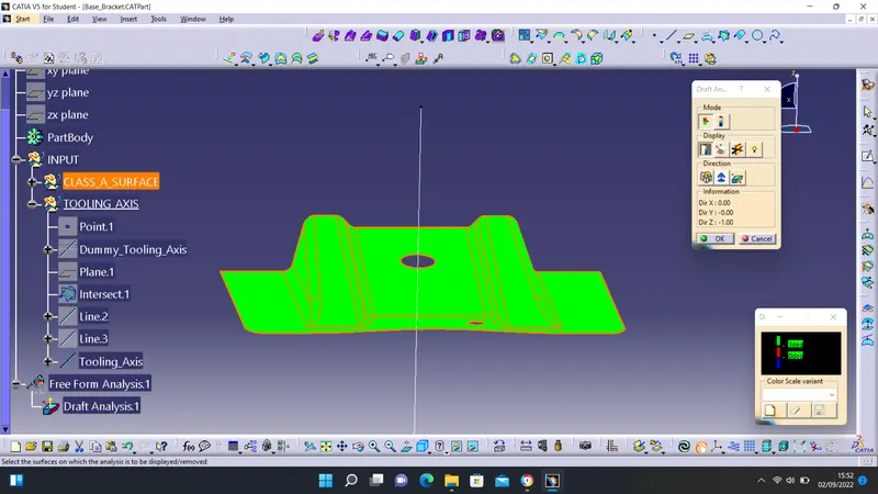
- check the draft angle
Draft Analysis: a draft angle of a minimum of 3 degrees is created. To perform a draft analysis, View Mode Customization is set to Material.
Creating class B surface
- extract the surfaces on class A, extrapolate, trim, and offset to a distance of 2.5mm to form B surface.
- to attain even thickness, the dimension of the fillet in class A is added to the offset distance to form the dimension for the class B fillet.
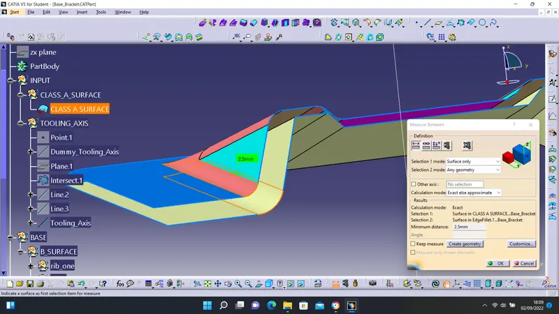
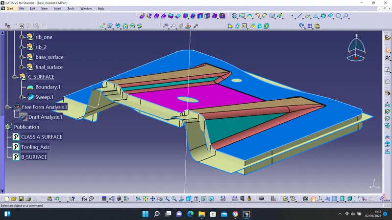
Creating class C surface: this is created by sweeping the boundary of class A to intersect with class B.
- sweep the boundary of class A
- sweep the boundary of both holes
- join class A and the sweep for both holes
- trim class C with (class A, sweep for both holes)
Creating a solid body
- switch to part design workbench
- Click close surface
- select the trim surface