Week 8 - Challenge 1 - Base Bracket Design
BASE BRACKET
Tooling Axis creation:
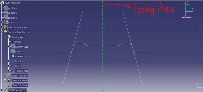
- Tooling axis is created for any component for the tool movement while manufacturing of the particular component.
- To create a tooling axis for the component, firstly the design engineer should analyze the best tooling direction for the movement of tool in manufacturing.
- Then create a point at the hole centre by selecting the circle/sphere/ellipse centre and also create a line passing through the point in the tooling direction.
- Let us assume the created line as dummy tooling line.
- At the same point, create a plane by selecting the 'parallel through point' option and select the preferrable plane direction.
- Now make intersection curve on the component using the created plane and component.
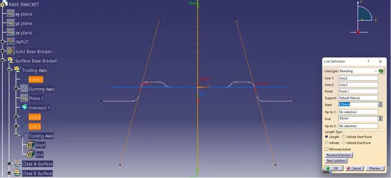
- The tool can easily move in horizontal and vertical directions to the tooling axis. For the slant directions, create a line by selecting point to point option. For the two slant curves, two lines should be created on both sides of the dummy tooling axis.
- Now create an another line by selecting the bisecting option and then select the two created lines on both sides. From this bisection method, we can obtain a line in the preferred tooling direction and this line is known as the Tooling Axis.
Draft Analysis:
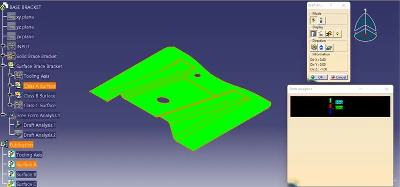
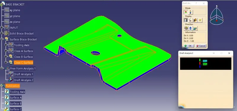
- Draft analysis is done on the class A surface and the final plastic surface component as shown below.
- The draft angle for plastic components ranges from 1/2 to 3 degrees and I have given a draft angle of 3 degree.
- The results of draft analysis with colour scale variation is shown below.
Class A surface Component 3D view
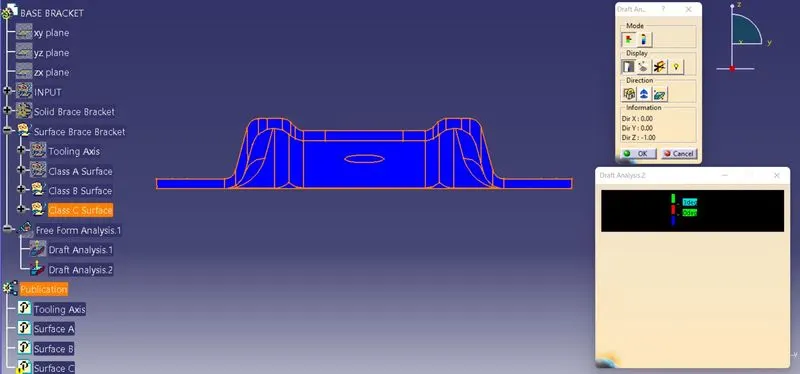
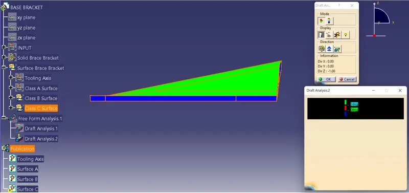
Component Front view Component Left view
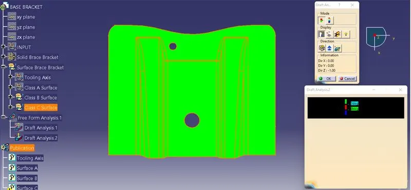
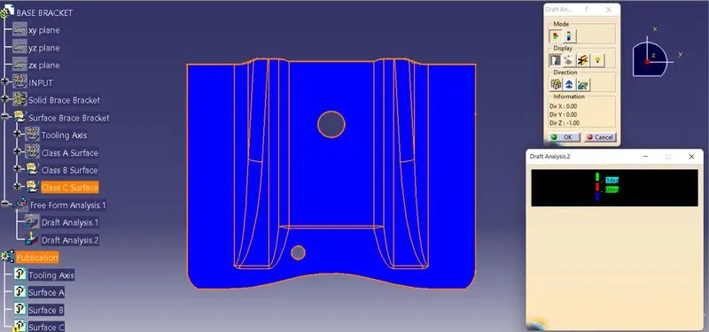
Component Top view Component Bottom view
Drawing views:
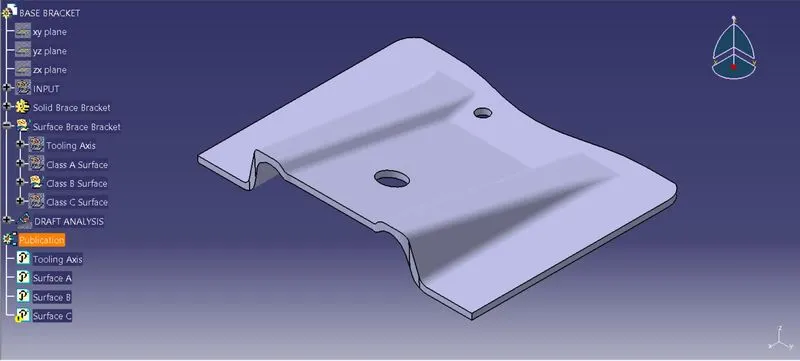
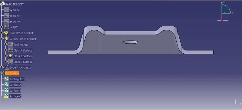
Trimetric view Front view
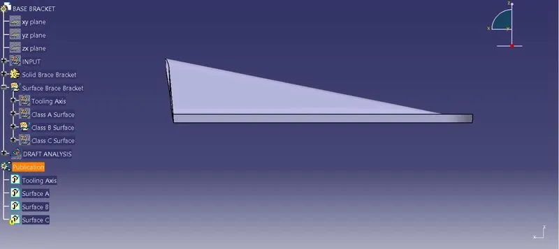
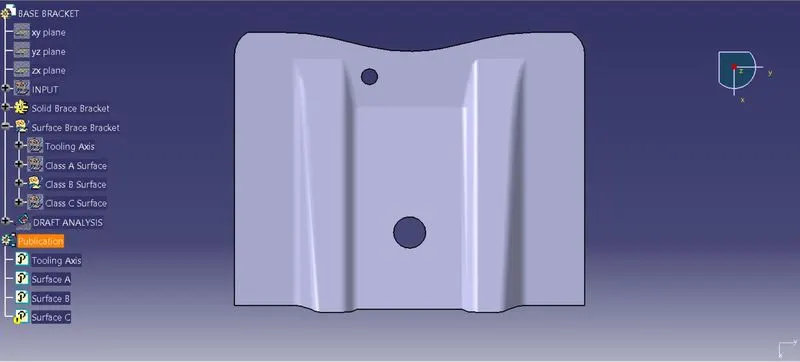
Right view Top view