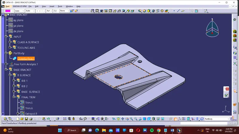
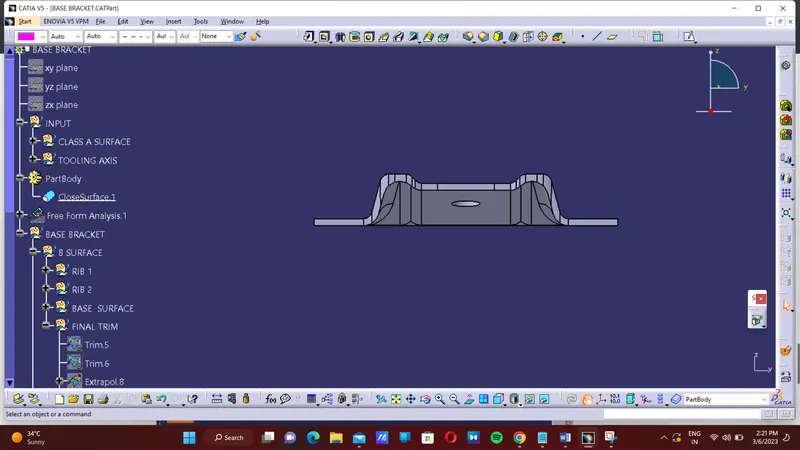
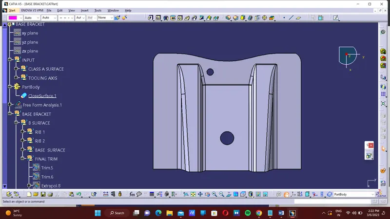
Week 8 - Challenge 1 - Base Bracket Design
Features used for design A-Class, B-Class, and C-Class
- Line
- Point
- Axis system
- Extrude
- Untrim
- Extrapolate
- Extract
- Boundary
- Join
- Swept
- Fillet
- Close surface
- Intersecting
- Publication
Specifications:
Base Bracket Thickness = 2.5mm
Minimum Draft Angle = 3 Degree
Class A Surface:
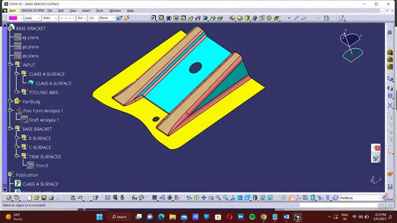
- Check the connectivity of the class A surface Ensure that there is no gap, Between the component using join command.
- we can visually check it or by clicking boundary command.
- It has 3 boundaries one outer and circle boundaries ,
- Therefore First check Completed
- Find the tooling axis of the component. The tooling axis is nothing but the mould opens or cavity opens.
- Check visually which is the best possible tooling axis.
- Check all three axis.
- Along x it possible but expensive and y is not possible.
- z is the best possible tooling axis.
TOOLING AXIS CREATION:
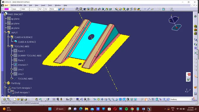
Using the intersection created lines will be created along the inclined walls, these lines are usedfor creation of tooling axis by bisecting method where are two lines and point will be selected as inputs.
Creating intersection for checking along X-axis
Using the tooling axis created along x-axis, these are used for creation of tooling axis by bisecting
method where the two lines and point will be selected as inputs.
Publication:
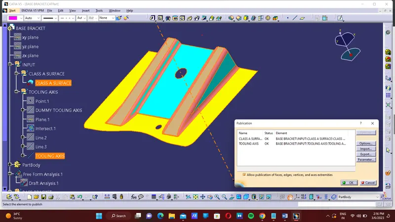
Publication is used to make easily accessible of the published components.
CLASS B SURFACE:
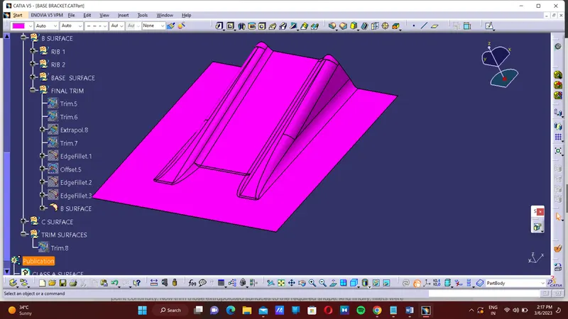
To create the class B surface, I considered the entire surface has 3 parts 'Rib-1, Rib-2, and Base surface'.
If we directly offset the class A surface, fillets may lead to cause an error, to avoid the errors we need to
extract the surfaces and untrim the extracted surfaces and extrapolate those untrimmed surfaces with
point continuity. Now trim those extrapolated surfaces to the required shape. And finally, fillets were
given to the final trim.
Class C Surface:
EXPLANATION ON BISECTING METHOD:
Bisecting method is basically use to find the proper tooling axis using thedummy tooling axis. In Bisecting method, bisecting line is used which eitherbisect the two line or it will show error which means the two lines are parallelto each other. In order to know whether the particular surface is toolable or not we intersect the surface with the respective plane and get a sketch whichconsist of two lines and with the help of bisecting line option we bisect theline which creates a line at the mid point of the two lines. Like wise we create tooling clearing axis for x and y which will be used to create the main tooling axis using the bisecting line option in in the line command.
Close Surface:
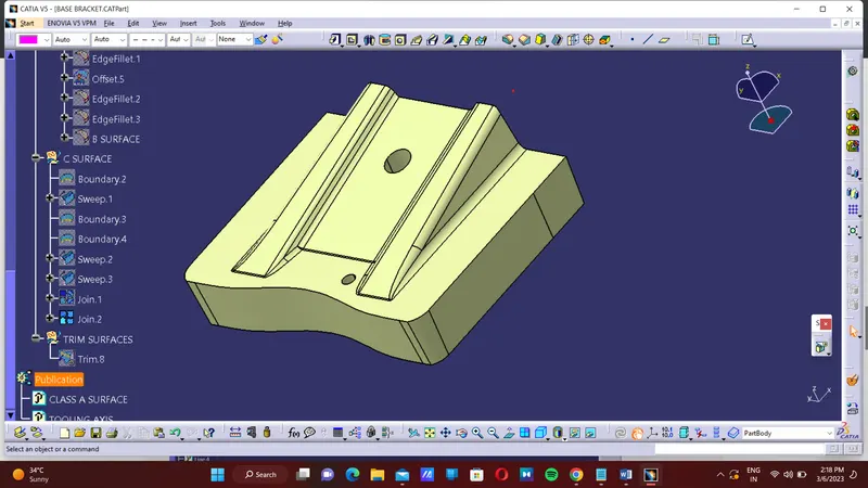
Finally we got the close surface through the part design.