Week 8 - Challenge 1 - Base Bracket Design
Report of Week 8 - Challenge 1 - Base Bracket Design
Aim
The main objective is to create the solid Base Bracket Plastic component using the given Class-A surface through Tooling axis and Draft analysis.
Contents
- Tooling axis (By bisecting method)
To create the 'Tooling Axis', the given class A should be observed thoroughly, For the given base bracket class A, Z-axis is the best suitable tooling axis, It is decided based on the complete visiblity of the class A. Then using the intersection made by the appropriate plane and the class A, We get a crossection sketch. The dummy axis is drawn on the z axis. Then the lines which are more or less parallel to the z axis are taken into consideration and drawn. By bisecting the two lines , As an output The Tooling axis is derived. 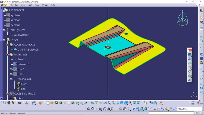
- Class A surface (given)
- Draft analysis of class A surface
To perform the draft analysis of class A surface, click on Insert >Analysis > Feature Draft Analysis
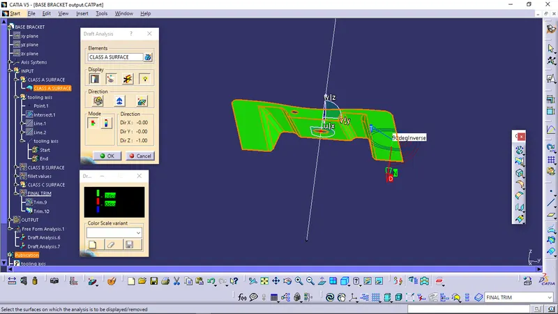
Once the draft analysis toolbar is opened, The compass was selected and placed on the tooling axis, Then go to the display block and select the 'Analysis under the running point' command to check the angle for different sides (ribs and inclined plane angles) on the class A surface. The color scale on the bottom visualizes, whether the draft angle meets the requirements or not (3 deg) by indicating the colors Green, Blue and Red.
Screenshots of the Draft analysis for the given Class-A surface with colour scale variant
- Class B surface
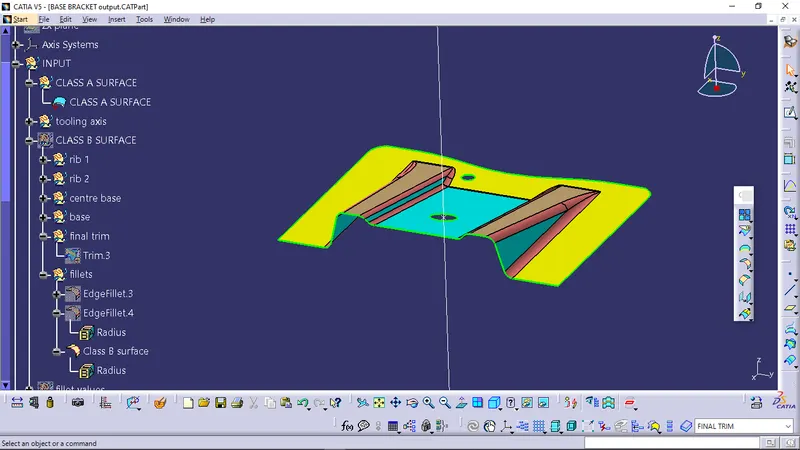
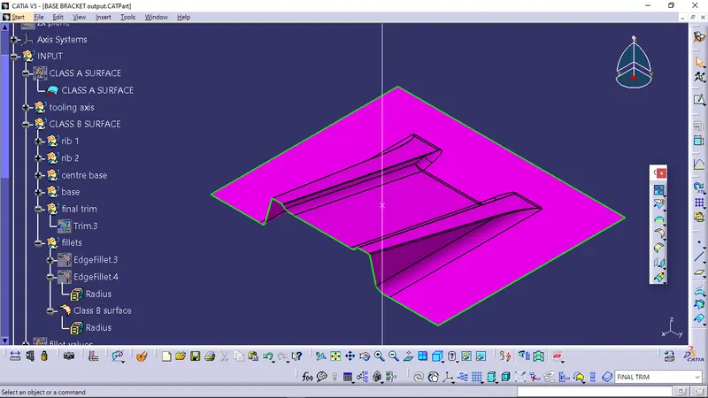
To create the class B surface from the class A, The entire surface has to be considered as 4 parts 'Rib-1, Rib-2, Base and Base surface'. If we directly offset the class A surface, fillets may lead to cause an error, To avoid the errors we need to extract the surfaces and untrim the extracted surfaces and extrapolate those untrimmed surfaces with point continuity. Now those extrapolated surfaces was trimmed to the required shape. And finally, fillets were given to the final trim.
- Class C surface
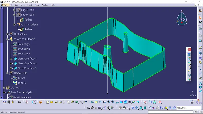
To create a class C surface, I used the sweep command by considering the outer boundary of the class A surface. In the sweep command > 'with draft direction', select the outer boundary and tooling axis, give 3 deg in the angle (the draft angle for a plastic component is 0.5 to 3 deg) and select the direction to sweep, in this condition the class B surface is under the class A surface so select the inside down arrow to sweep. The same procedure is repeated for the two circles on the class A surface.
- Surface output of Base bracket
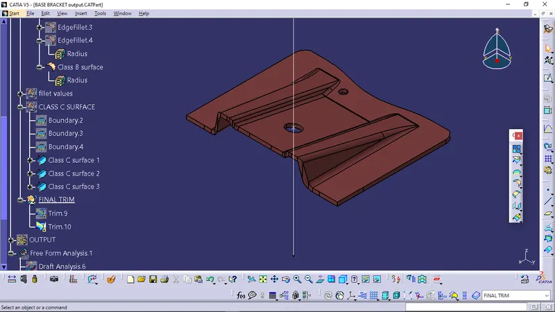
Then the closed surface was created by using the 'Trim' operation consisting the Class A , Class B and Class C surfaces.
- Solid Base Bracket
To create the solid base barcket, Jump to part design workbench and select the closesurface option in the Surface based feature.
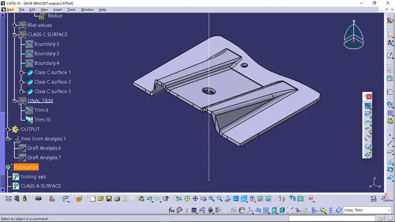
- Draft analysis of Solid Base Bracket
To perform the draft analysis of solid base bracket, click on Insert >Analysis > Draft Analysis
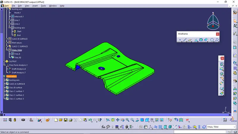
Once the draft analysis toolbar is opened, The compass was selected and placed on the tooling axis, Then go to the display block and select the 'Analysis under the running point' command to check the angle for different sides on the Solid Base Bracket. The color scale on the bottom visualizes, whether the draft angle meets the requirements or not (3 deg) by indicating the colors Green, Blue and Red.
Screenshots of the Draft analysis for the final plastic component with colour scale variant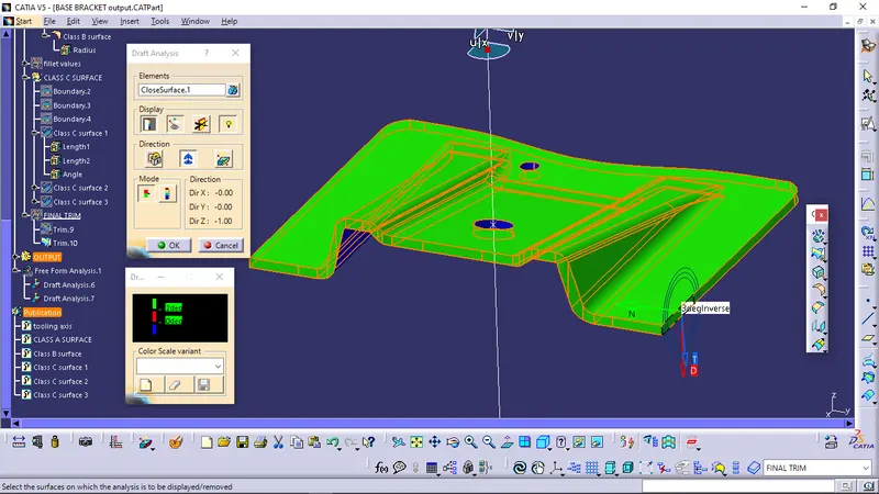
- Screenshot of the Tree structure
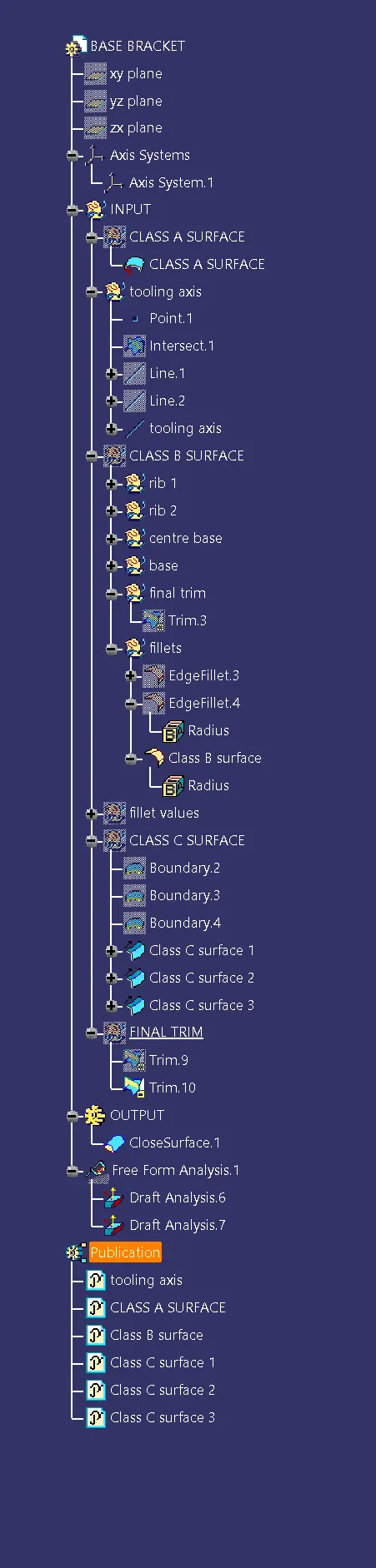
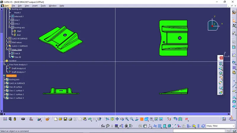
- Screenshots of the solid model with the proper colour code of the draft angle in various orientations (Isometric, Front, Side, and Top View)