Week 8 - Challenge 1 - Base Bracket Design
Aim:
- To Create the Base Bracket Plastic component through the given Class-A surface.To begin with, the tooling axis for the given Class-A Surface should be created meeting the requirements of the draft angle and at the end perform the Draft analysis on the model.
Class 'A' Surface:
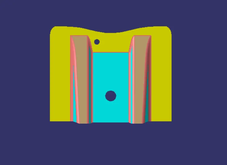
Steps Followed After Receiving Class-A surface:
- Check the connectivity of the surface using joins and boundary and ensure there is no gap between the surfaces.
- After checking the connectivity define the Tooling axis of the given surface.
1.Tooling Axis:
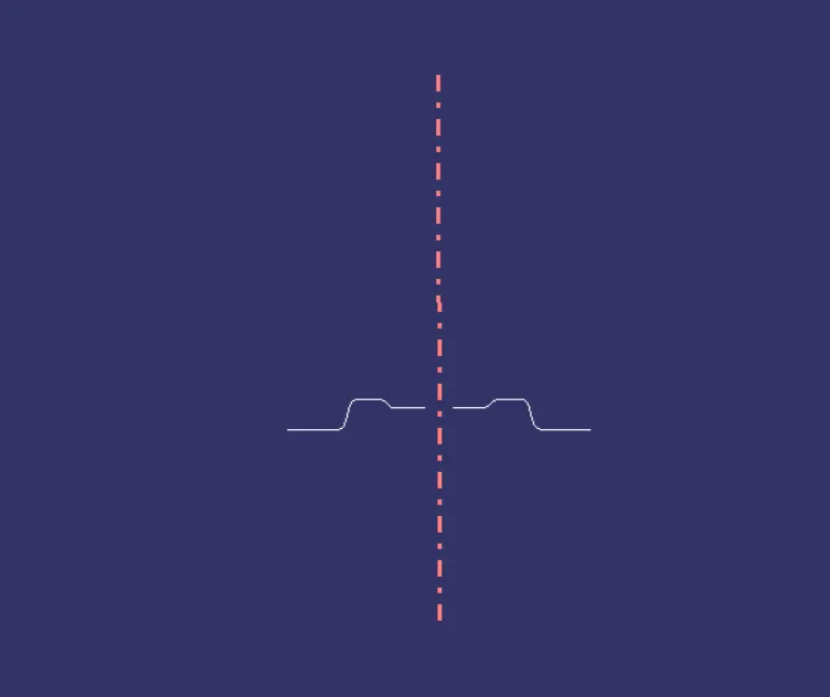
- The direction in which the mould open and closes is the tooling axis.
- The mould is built from two separate halves (Core and Cavity) and tooling direction basically defines the direction of mould pulls apart. Tooling direction is known as primary direction.
- Basically Tooling axis should be determined in flat length surface or surface having Hole on it. Create a point and use line command and drwa a dummy tooling axis
2.Bisecting Line:
- After determing the Dummy tooling axis , identify a plane where we are going to do more operations and using intersection command take the plane as refernce intersect the class A surface.
- And Look for thr profile which will create a problem and extend the profile using line command.
- Then create the bisecting line between the two lines.
- Thus the Tooling Axis line is created
3.Draft Analysis:
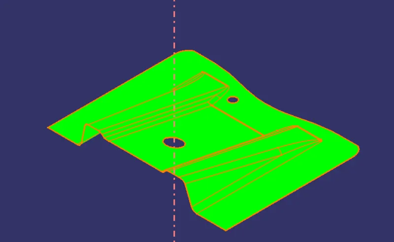
- The Draft Analysis command enables you to detect if the part you drafted will be easily removed. This type of analysis is performed based on color ranges identifying zones on the analyzed element where the deviation from the draft direction at any point, corresponds to specified values.
- The colour scale on the bottom visualizes, whether the draft angle meets the requirements or not (3 deg) by indicating the colours Green, Blue and Red. We need to align and fix the compass to the tooling axis then the draft angle analysis will be checked out.
Class 'B' Surface:

- Intially extract the rib surface of the class A surface and untrim the surfaces
- And extrapolate the surface for the required dimensions and offset the surface to 2.5mm (according to the thickness)
- And trim the surfaces for the required shape
- Do the same for the other base surfaces and trim with rib surfaces for the required shapes.
Class C Surface:
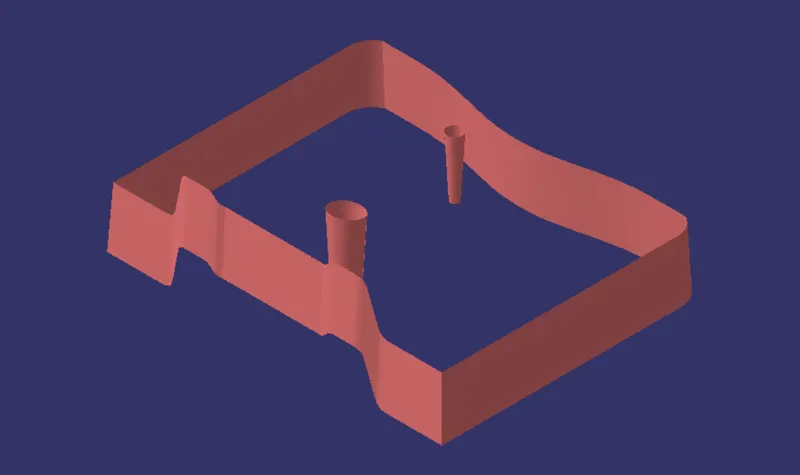
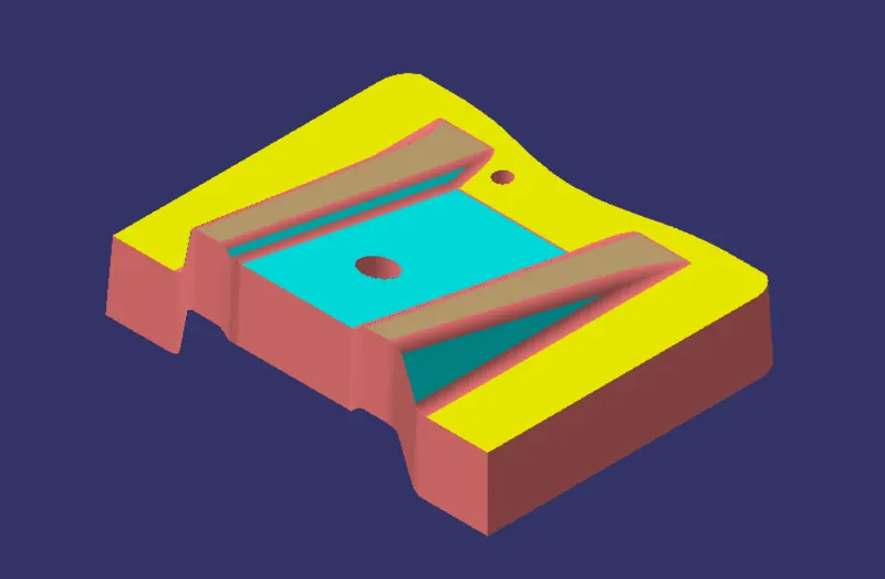
- Take outer boundary of Class-A surface and using Sweep command Class 'C' surface is obtained.
Final Solid :
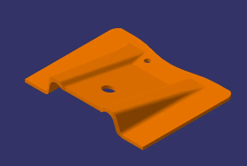
Draft Analysis of the Final Solid:
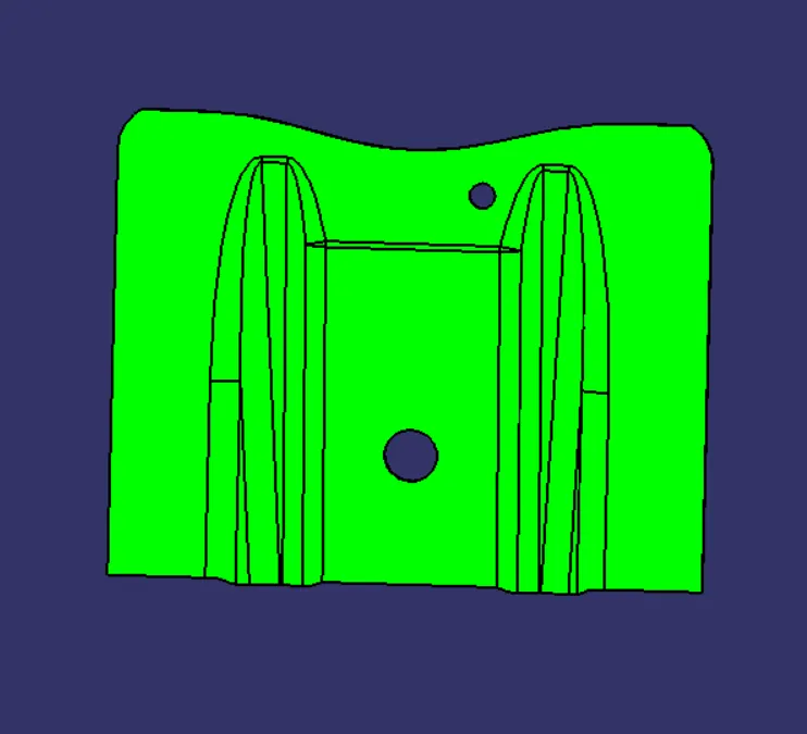
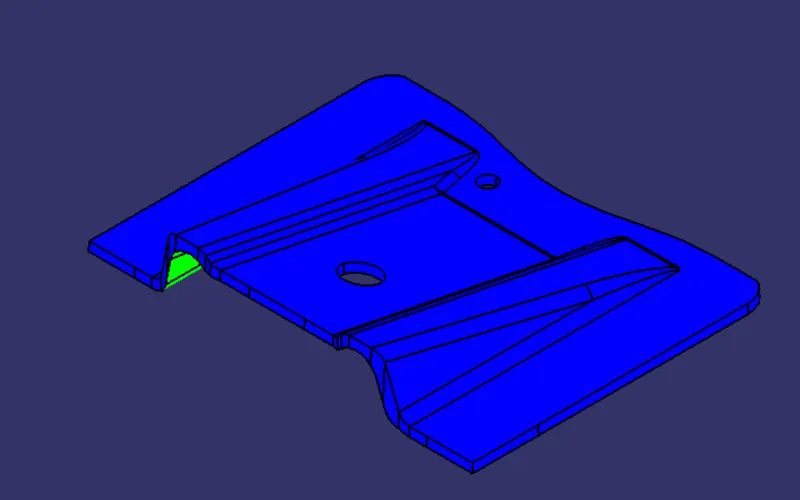
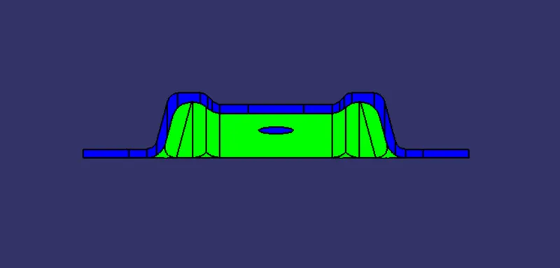
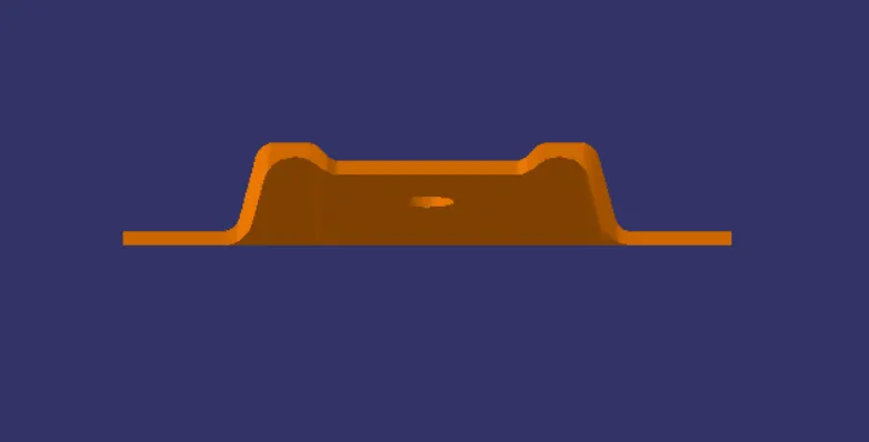
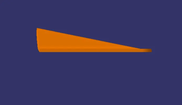
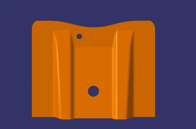
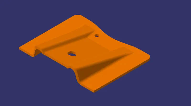
Various orientations of Final Solid Body:
Front View:
SideView:

Top View:
Isometric View:
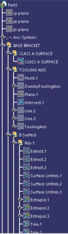
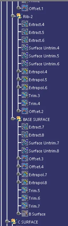
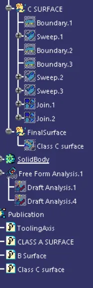
TreeStructure of the Geometry: