Week 8 - BlockMesh Drill down challenge
OBJECTIVE:
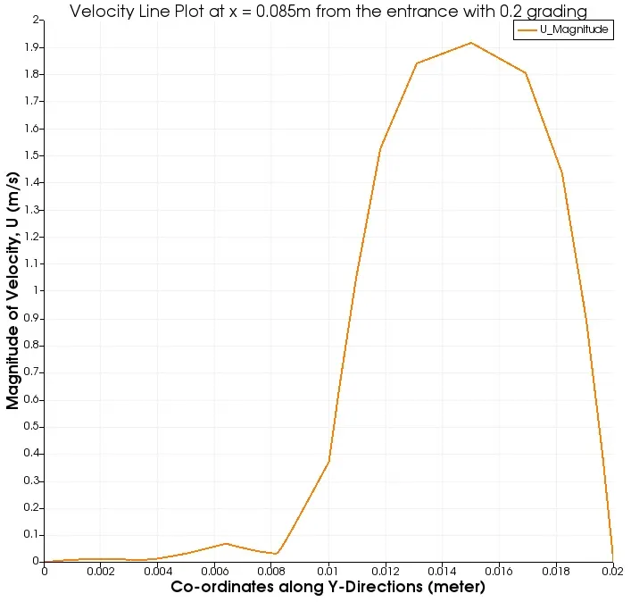
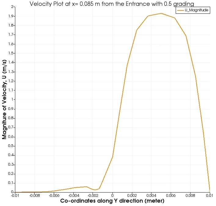
1. To simulate 2D laminar incompressible flow through backwards-facing step using Finite Volume Method and to plot the velocity contour and line plot of velocity at the step.
2. To create the geometry using blockMesh utility
3. To a solver which is cable of solving a laminar and incompressible flow
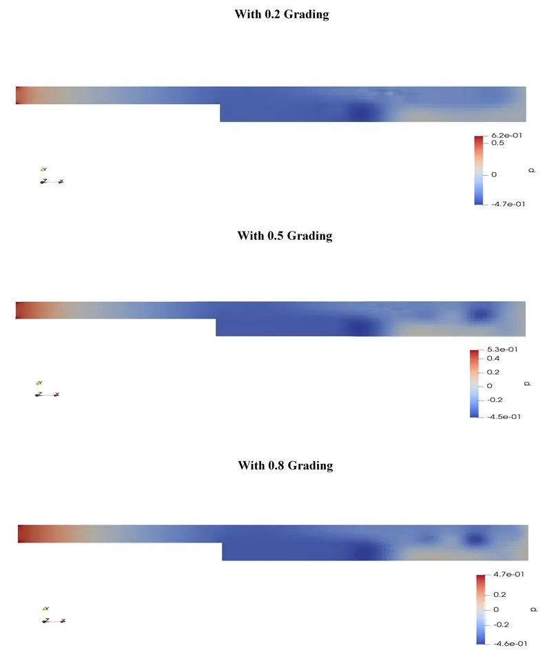
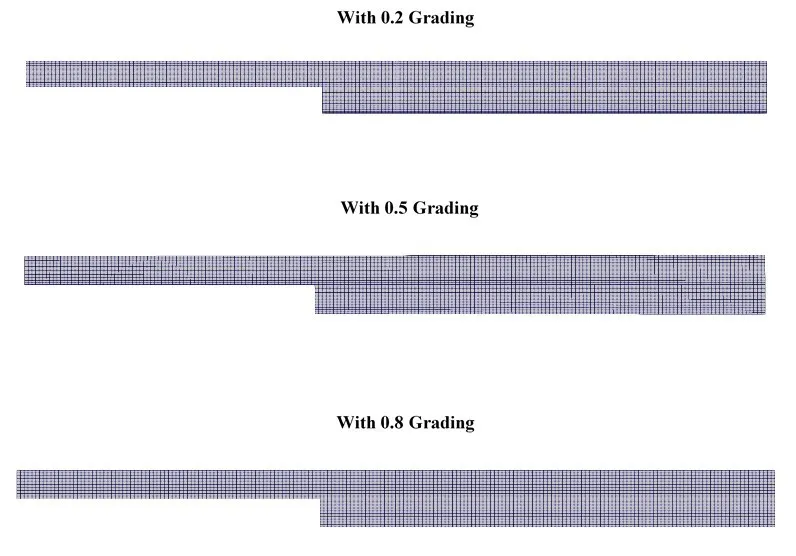
4. To observe the effect of mesh grading on the final velocity and pressure plots
THEORY & ALGORITHM:
Case set up Structure:
To set up any simulation in OpenFOAM there is 3 major folder.
1. System: Defines the geometry, the solver, the discretization schemes and the major simulation parameters like time steps, CFL number etc.
2. Constant: Here all the constant along with the dimensions present in the Governing equations are defined.
3. 0: Here we have to define all the initial parameters.
Step:1: GEOMETRY CREATION:
So the first step would be to create the geometry using blockMesh utility of OpenFOAM. for that we need to segment the geometry into multiple blocks in the following way.
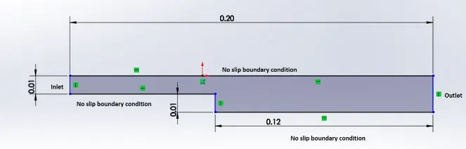
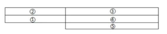
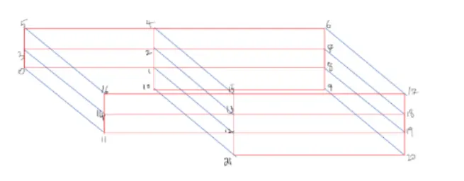
The number of cells along the x-direction is 200, in the y-direction is 10 and in the z-direction, the cell number has been considered 1(as we are considering 2D flow case).
In the case of Finite Volume Method (FVM) even in the case of 2D flow, we have to consider a 3D block with minimal thickness. So we have 2 sides, front and back. The vvertices of the back plan is first numbered in the chronological order and then the front plane vertices are numbered accordingly.
Using these vertices the small building blocks are defined using blockMesh utility which are again connected to create the desired geometry.
After all these, the mesh generation is done and along with that, the simple grading is implemented in such a way that we can capture the effect near the walls very clearly.
All these are accomplished using the blcokMeshDict file.
Step: 2: SETTING UP THE GOVERNING EQUATION & THE DISCRETIZATION SCHEMES: (Solver)
Discretization is done using 'fvSchemes' file present the 'system' folder and the solver which is used here is defined in the 'fvSolution'. The solver used here is called icoFoam which is a pressure-based solver.
Step: 3: SETTING UP THE INITIAL PARAMETERS & CONTROL PARAMETERS
We need the '0' folder to set up the initial parameters and the controlDict in the system folder to set up the control parameters. Here we explicitly mention the solver we are going to use while solving the governing equations. Particularly, we need to set the time-step and the mesh in such a way that the max CFL in every time step remains less than 1. In the case of OpenFOAM, CFL number is considered in terms of flux like as follows:
`CFL =(u/_\t)/(/_\x) = (uA/_\t)/(A/_\x) = (phi/_\t)/(/_\V)`
Step: 4: POST-PROCESSING:
After setting up the case, the following commands are typed to initiate the utilities.
1. For creating the geometry: blockMesh
2. For checking whether the mesh quality is good or not: checkMesh
3. calling the solver: icoFoam
4. Lastly for visualizing the results, we need to use a 3rd party tool call paraview which is called by: paraFoam
Using paraview we can create the contours and line plots.
CASE SET UP FILES:
a. Setting up the system folder:
1. blockMeshDict:
This code is for 0.2 mesh grading
/*--------------------------------*- C++ -*----------------------------------*\
  =========                 |
  \\      /  F ield         | OpenFOAM: The Open Source CFD Toolbox
   \\    /   O peration     | Website:  https://openfoam.org
    \\  /    A nd           | Version:  7
     \\/     M anipulation  |
\*---------------------------------------------------------------------------*/
FoamFile
{
    version     2.0;
    format      ascii;
    class       dictionary;
    object      blockMeshDict;
}
// * * * * * * * * * * * * * * * * * * * * * * * * * * * * * * * * * * * * * //

convertToMeters 0.001;

vertices
(
    (0 0 0)
    (80 0 0)
    (80 5 0)
    (0 5 0)
    (80 10 0)
    (0 10 0)
    (200 10 0)
    (200 5 0)
    (200 0 0)
    (200 -10 0)
    (80 -10 0)
    (0 0 0.1)
    (80 0 0.1)
    (80 5 0.1)
    (0 5 0.1)
    (80 10 0.1)
    (0 10 0.1)
    (200 10 0.1)
    (200 5 0.1)
    (200 0 0.1)
    (200 -10 0.1)
    (80 -10 0.1)
);

blocks
(
    hex (0 1 2 3 11 12 13 14) (80 5 1) simpleGrading (1 5 1)
    hex (3 2 4 5 14 13 15 16) (80 5 1) simpleGrading (1 0.2 1)
    hex (2 7 6 4 13 18 17 15) (120 5 1) simpleGrading (1 0.2 1)
    hex (1 8 7 2 12 19 18 13) (120 5 1) simpleGrading (1 5 1)
    hex (10 9 8 1 21 20 19 12) (120 10 1) simpleGrading (1 5 1)
);

edges
(
);

boundary
(
    inlet
    {
        type patch;
        faces
        (
            (0 11 14 3)
	    (5 3 14 16)
        );
    }
    outlet
    {
        type patch;
        faces
        (
            (7 6 17 18)
            (8 7 18 19)
            (9 8 19 20)
        );
    }
    front
    {
        type empty;
        faces
        (
            (15 16 14 13)
            (13 14 11 12)
            (17 15 13 18)
            (18 13 12 19)
            (19 12 21 20)
        );
    }
    back
    {
        type empty;
        faces
        (
            (5 4 2 3)
            (3 2 1 0)
            (4 6 7 2)
            (2 7 8 1)
            (1 8 9 10)
        );
    }
    top
    {
        type wall;
        faces
        (
            (5 16 15 4)
            (4 15 17 6)
        );
    }
    bottom
    {
        type wall;
        faces
        (
            (11 0 1 12)
            (21 10 9 20)
            (12 1 10 21)
        );
    }
);

mergePatchPairs
(
);

// ************************************************************************* //
2. controlDict:
/*--------------------------------*- C++ -*----------------------------------*\
  =========                 |
  \\      /  F ield         | OpenFOAM: The Open Source CFD Toolbox
   \\    /   O peration     | Website:  https://openfoam.org
    \\  /    A nd           | Version:  7
     \\/     M anipulation  |
\*---------------------------------------------------------------------------*/
FoamFile
{
    version     2.0;
    format      ascii;
    class       dictionary;
    location    "system";
    object      controlDict;
}
// * * * * * * * * * * * * * * * * * * * * * * * * * * * * * * * * * * * * * //

application     icoFoam;

startFrom       startTime;

startTime       0;

stopAt          endTime;

endTime         0.5;

deltaT          0.0001;

writeControl    timeStep;

writeInterval   20;

purgeWrite      0;

writeFormat     ascii;

writePrecision  6;

writeCompression off;

timeFormat      general;

timePrecision   6;

runTimeModifiable true;


// ************************************************************************* //
3. fvSchemes:
/*--------------------------------*- C++ -*----------------------------------*\
  =========                 |
  \\      /  F ield         | OpenFOAM: The Open Source CFD Toolbox
   \\    /   O peration     | Website:  https://openfoam.org
    \\  /    A nd           | Version:  7
     \\/     M anipulation  |
\*---------------------------------------------------------------------------*/
FoamFile
{
    version     2.0;
    format      ascii;
    class       dictionary;
    location    "system";
    object      fvSchemes;
}
// * * * * * * * * * * * * * * * * * * * * * * * * * * * * * * * * * * * * * //

ddtSchemes
{
    default         Euler;
}

gradSchemes
{
    default         Gauss linear;
    grad(p)         Gauss linear;
}

divSchemes
{
    default         none;
    div(phi,U)      Gauss linear;
}

laplacianSchemes
{
    default         Gauss linear orthogonal;
}

interpolationSchemes
{
    default         linear;
}

snGradSchemes
{
    default         orthogonal;
}


// ************************************************************************* //
4. fvSolutions:
/*--------------------------------*- C++ -*----------------------------------*\
  =========                 |
  \\      /  F ield         | OpenFOAM: The Open Source CFD Toolbox
   \\    /   O peration     | Website:  https://openfoam.org
    \\  /    A nd           | Version:  7
     \\/     M anipulation  |
\*---------------------------------------------------------------------------*/
FoamFile
{
    version     2.0;
    format      ascii;
    class       dictionary;
    location    "system";
    object      fvSolution;
}
// * * * * * * * * * * * * * * * * * * * * * * * * * * * * * * * * * * * * * //

solvers
{
    p
    {
        solver          PCG;
        preconditioner  DIC;
        tolerance       1e-06;
        relTol          0.05;
    }

    pFinal
    {
        $p;
        relTol          0;
    }

    U
    {
        solver          smoothSolver;
        smoother        symGaussSeidel;
        tolerance       1e-05;
        relTol          0;
    }
}

PISO
{
    nCorrectors     2;
    nNonOrthogonalCorrectors 0;
    pRefCell        0;
    pRefValue       0;
}


// ************************************************************************* //
b. Setting up the constant Folder:
1. transportProperties:
/*--------------------------------*- C++ -*----------------------------------*\
  =========                 |
  \\      /  F ield         | OpenFOAM: The Open Source CFD Toolbox
   \\    /   O peration     | Website:  https://openfoam.org
    \\  /    A nd           | Version:  7
     \\/     M anipulation  |
\*---------------------------------------------------------------------------*/
FoamFile
{
    version     2.0;
    format      ascii;
    class       dictionary;
    location    "constant";
    object      transportProperties;
}
// * * * * * * * * * * * * * * * * * * * * * * * * * * * * * * * * * * * * * //

nu              [0 2 -1 0 0 0 0] 1.868e-05;


// ************************************************************************* //
c. Setting up the initial conditions or '0' Folder:
1. Initials conditions for the velocity, U:
/*--------------------------------*- C++ -*----------------------------------*\
  =========                 |
  \\      /  F ield         | OpenFOAM: The Open Source CFD Toolbox
   \\    /   O peration     | Website:  https://openfoam.org
    \\  /    A nd           | Version:  7
     \\/     M anipulation  |
\*---------------------------------------------------------------------------*/
FoamFile
{
    version     2.0;
    format      ascii;
    class       volVectorField;
    object      U;
}
// * * * * * * * * * * * * * * * * * * * * * * * * * * * * * * * * * * * * * //

dimensions      [0 1 -1 0 0 0 0];

internalField   uniform (0 0 0);

boundaryField
{
    inlet
    {
        type            fixedValue;
        value           uniform (1.5 0 0);
    }

    outlet
    {
        type            zeroGradient;
    }

    top
    {
        type            noSlip;
    }

    bottom
    {
        type            noSlip;
    }

    front
    {
        type            empty;
    }

    back
    {
        type            empty;
    }
}

// ************************************************************************* //
2. Initial Conditions for the Pressure, p:
/*--------------------------------*- C++ -*----------------------------------*\
  =========                 |
  \\      /  F ield         | OpenFOAM: The Open Source CFD Toolbox
   \\    /   O peration     | Website:  https://openfoam.org
    \\  /    A nd           | Version:  7
     \\/     M anipulation  |
\*---------------------------------------------------------------------------*/
FoamFile
{
    version     2.0;
    format      ascii;
    class       volScalarField;
    object      p;
}
// * * * * * * * * * * * * * * * * * * * * * * * * * * * * * * * * * * * * * //

dimensions      [0 2 -2 0 0 0 0];

internalField   uniform 0;

boundaryField
{
    inlet
    {
        type            zeroGradient;
    }

    outlet
    {
        type            fixedValue;
	value		uniform 0;
    }

    top
    {
    	type		zeroGradient;
    }

    bottom
    {
    	type		zeroGradient;
    }

    front
    {
        type            empty;
    }

    back
    {
    	type		empty;
    }

}

// ************************************************************************* //
Outputs:
Velocity Contour
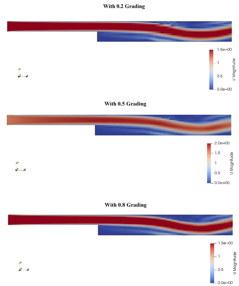
Pressure Contour
Mesh
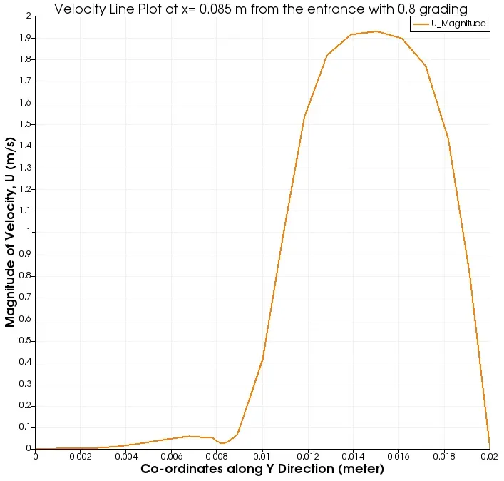
Comparison of the velocity Line Plots
Discussion of result:
1. So with the change in grading value, we hardly find any difference in the end results. The only difference we see is in the velocity line plots. With the increase in mesh grading the velocity contours smoothen up. The reason is as the grading increases the mesh size becomes small and the number of cell increases. This contributes to the smoothness of the end results.
2. As expected the pressure contours shows a gradual decrease in pressure and then at the end the pressure slightly increases which is caused by the decrease in the mean velocity at the outlet.