Flow over a backward facing step with different grading factors
OBJECTIVE:
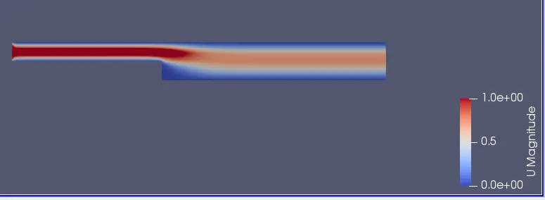
The main objective of the challenge is to simulate the flow over a backward facing step with grading factors 0.2,0.5 and 0.8 and to compare the velocity magnitude contours also to observe the changes in the velocity magnitude profile as a function of mesh grading factor ,measured at 0.085m from the inlet for the given geometry.
Geometry:
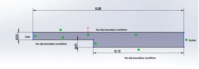
Generation of the block mesh:
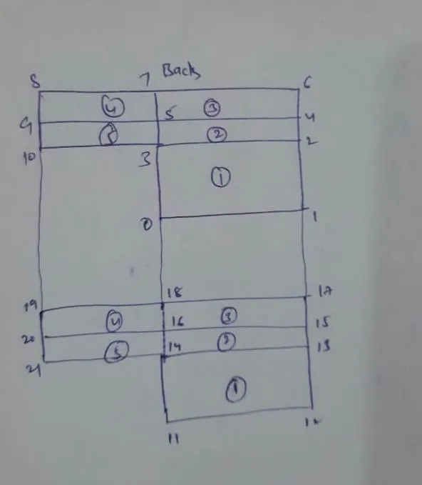
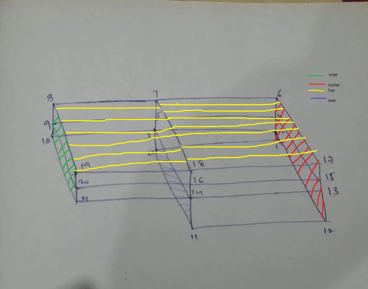
In the above figure Bottom walls are not represented ,whose faces are exactly opposite to top faces.
Initially, the geometry is divided in to 5 bocks as shown in the above figure and all the vertices are indexed as shown.Every vertex is defined in 'cartesian co-ordinate system', where origin is taken at step .
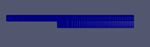
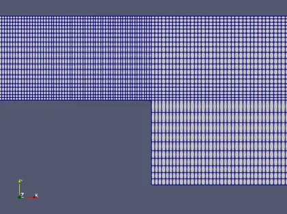
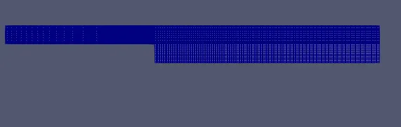
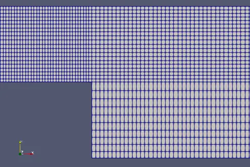
Block topology is defined as 'hex' which means we are using hexahedral blocks which generates the rectangular mesh and number of cells in the x-direction are 200 and y-direction 10 with simple grading of garding factor 0.2,0.5,0.8.
while defining blocks the area vector should point outwards this can be achieved by using 'right hand thumb rule'.
Boundary conditions:
After defining the block topology boundry conditions needs to be specified , in this case inlet and outlet type is defined as 'patch', top and bottom walls type is defined as 'fixedwalls' and front ,backtype is defined as 'empty', as we assume there is no flow in the z-direction. All the patch pairs are merged to generate complete mesh.
blockMeshDict:
for grading factor =0.2
/*--------------------------------*- C++ -*----------------------------------*
  =========                 |
  \      /  F ield         | OpenFOAM: The Open Source CFD Toolbox
   \    /   O peration     | Website:  https://openfoam.org
    \  /    A nd           | Version:  7
     \/     M anipulation  |
*---------------------------------------------------------------------------*/
FoamFile
{
    version     2.0;
    format      ascii;
    class       dictionary;
    object      blockMeshDict;
}
// * * * * * * * * * * * * * * * * * * * * * * * * * * * * * * * * * * * * * //

convertToMeters 0.001;

vertices
(
    (0 0 0)
    (120 0 0)
    (120 10 0)
    (0 10 0)
    (120 15 0)
    (0 15 0)
    (120 20 0)
    (0 20 0)
    (-80 20 0)
    (-80 15 0)
    (-80 10 0)
    (0 0 1)
    (120 0 1)
    (120 10 1)
    (0 10 1)
    (120 15 1)
    (0 15 1)
    (120 20 1)
    (0 20 1)
    (-80 20 1)
    (-80 15 1)
    (-80 10 1)

);

blocks
(
    hex (0 1 2 3 11 12 13 14) (200 10 1) simpleGrading (5 5 1)
    hex (3 2 4 5 14 13 15 16) (200 10 1) simpleGrading (5 5 1)
    hex (5 4 6 7 16 15 17 18) (200 10 1) simpleGrading (5 0.2 1)
    hex (9 5 7 8 20 16 18 19) (200 10 1) simpleGrading (0.2 0.2 1)
    hex (10 3 5 9 21 14 16 20) (200 10 1) simpleGrading (0.2 5 1)

);

edges
(
);

boundary
(
    inletWall
    {
        type patch;
        faces
        (
            (10 21 20 9)
            (9 20 19 8)
        );
    }
    outletWall
    {
        type patch;
        faces
        (
            (1 2 13 12)
            (2 4 15 13)
            (4 6 17 15)
        );
    }
    fixedWalls
    {
        type wall;
        faces
        (
            (18 17 6 7)
            (19 18 7 8)
            (11 14 3 0)
            (12 1 0 11)
            (21 14 3 10)
        );
    }
    frontAndBack
    {
        type empty;
        faces
        (
            (11 12 13 14)
            (14 13 15 16)
            (16 15 17 18)
            (20 16 18 19)
            (21 14 16 20)
            (0 3 2 1)
            (3 5 4 2)
            (5 7 6 4)
            (10 9 5 3)
            (9 8 7 5)

        );
    }
);

mergePatchPairs
(
);
// ************************************************************************* //
for grading factor=0.5
/*--------------------------------*- C++ -*----------------------------------*
  =========                 |
  \      /  F ield         | OpenFOAM: The Open Source CFD Toolbox
   \    /   O peration     | Website:  https://openfoam.org
    \  /    A nd           | Version:  7
     \/     M anipulation  |
*---------------------------------------------------------------------------*/
FoamFile
{
    version     2.0;
    format      ascii;
    class       dictionary;
    object      blockMeshDict;
}
// * * * * * * * * * * * * * * * * * * * * * * * * * * * * * * * * * * * * * //

convertToMeters 0.001;

vertices
(
    (0 0 0)
    (120 0 0)
    (120 10 0)
    (0 10 0)
    (120 15 0)
    (0 15 0)
    (120 20 0)
    (0 20 0)
    (-80 20 0)
    (-80 15 0)
    (-80 10 0)
    (0 0 1)
    (120 0 1)
    (120 10 1)
    (0 10 1)
    (120 15 1)
    (0 15 1)
    (120 20 1)
    (0 20 1)
    (-80 20 1)
    (-80 15 1)
    (-80 10 1)

);

blocks
(
    hex (0 1 2 3 11 12 13 14) (200 10 1) simpleGrading (2 2 1)
    hex (3 2 4 5 14 13 15 16) (200 10 1) simpleGrading (2 2 1)
    hex (5 4 6 7 16 15 17 18) (200 10 1) simpleGrading (2 0.5 1)
    hex (9 5 7 8 20 16 18 19) (200 10 1) simpleGrading (0.5 0.5 1)
    hex (10 3 5 9 21 14 16 20) (200 10 1) simpleGrading (0.5 2 1)

);

edges
(
);

boundary
(
    inletWall
    {
        type patch;
        faces
        (
            (10 21 20 9)
            (9 20 19 8)
        );
    }
    outletWall
    {
        type patch;
        faces
        (
            (1 2 13 12)
            (2 4 15 13)
            (4 6 17 15)
        );
    }
    fixedWalls
    {
        type wall;
        faces
        (
            (18 17 6 7)
            (19 18 7 8)
            (11 14 3 0)
            (12 1 0 11)
            (21 14 3 10)
        );
    }
    frontAndBack
    {
        type empty;
        faces
        (
            (11 12 13 14)
            (14 13 15 16)
            (16 15 17 18)
            (20 16 18 19)
            (21 14 16 20)
            (0 3 2 1)
            (3 5 4 2)
            (5 7 6 4)
            (10 9 5 3)
            (9 8 7 5)

        );
    }
);

mergePatchPairs
(
);
// ************************************************************************* //
for grading factor=0.8
/*--------------------------------*- C++ -*----------------------------------*
  =========                 |
  \      /  F ield         | OpenFOAM: The Open Source CFD Toolbox
   \    /   O peration     | Website:  https://openfoam.org
    \  /    A nd           | Version:  7
     \/     M anipulation  |
*---------------------------------------------------------------------------*/
FoamFile
{
    version     2.0;
    format      ascii;
    class       dictionary;
    object      blockMeshDict;
}
// * * * * * * * * * * * * * * * * * * * * * * * * * * * * * * * * * * * * * //

convertToMeters 0.001;

vertices
(
    (0 0 0)
    (120 0 0)
    (120 10 0)
    (0 10 0)
    (120 15 0)
    (0 15 0)
    (120 20 0)
    (0 20 0)
    (-80 20 0)
    (-80 15 0)
    (-80 10 0)
    (0 0 1)
    (120 0 1)
    (120 10 1)
    (0 10 1)
    (120 15 1)
    (0 15 1)
    (120 20 1)
    (0 20 1)
    (-80 20 1)
    (-80 15 1)
    (-80 10 1)

);

blocks
(
    hex (0 1 2 3 11 12 13 14) (200 10 1) simpleGrading (1.25 1.25 1)
    hex (3 2 4 5 14 13 15 16) (200 10 1) simpleGrading (1.25 1.25 1)
    hex (5 4 6 7 16 15 17 18) (200 10 1) simpleGrading (1.25 0.8 1)
    hex (9 5 7 8 20 16 18 19) (200 10 1) simpleGrading (0.8 0.8 1)
    hex (10 3 5 9 21 14 16 20) (200 10 1) simpleGrading (0.8 1.25 1)

);

edges
(
);

boundary
(
    inletWall
    {
        type patch;
        faces
        (
            (10 21 20 9)
            (9 20 19 8)
        );
    }
    outletWall
    {
        type patch;
        faces
        (
            (1 2 13 12)
            (2 4 15 13)
            (4 6 17 15)
        );
    }
    fixedWalls
    {
        type wall;
        faces
        (
            (18 17 6 7)
            (19 18 7 8)
            (11 14 3 0)
            (12 1 0 11)
            (21 14 3 10)
        );
    }
    frontAndBack
    {
        type empty;
        faces
        (
            (11 12 13 14)
            (14 13 15 16)
            (16 15 17 18)
            (20 16 18 19)
            (21 14 16 20)
            (0 3 2 1)
            (3 5 4 2)
            (5 7 6 4)
            (10 9 5 3)
            (9 8 7 5)

        );
    }
);

mergePatchPairs
(
);
// ************************************************************************* //
Mesh generated:
for grading factor =0.2
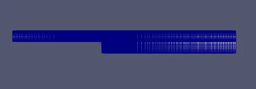
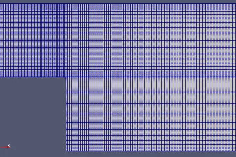
5 blocks are used to generate the geometry because to satisfy the given criteria of having fine mesh at walls and the important point to be remembered while gradind is to have correct alignment of mesh for the blocks 2 5 and 4 3 to flow information from the inlet section to outlet section if proper grading is not used then information is not going to flow .
In the second figure mesh alignment is shown .
Velocity :
/*--------------------------------*- C++ -*----------------------------------*
  =========                 |
  \      /  F ield         | OpenFOAM: The Open Source CFD Toolbox
   \    /   O peration     | Website:  https://openfoam.org
    \  /    A nd           | Version:  7
     \/     M anipulation  |
*---------------------------------------------------------------------------*/
FoamFile
{
    version     2.0;
    format      ascii;
    class       volVectorField;
    object      U;
}
// * * * * * * * * * * * * * * * * * * * * * * * * * * * * * * * * * * * * * //

dimensions      [0 1 -1 0 0 0 0];

internalField   uniform (0 0 0);

boundaryField
{
    inletWall
    {
        type            fixedValue;
        value           uniform (1 0 0);
    }

    outletWall
    {
	type            zeroGradient;
    }

    fixedWalls
    {
        type            noSlip;
    }

    frontAndBack
    {
        type            empty;
    }
}

// ************************************************************************* //
Velocity at the inlet is given as 1 m/s ,type as fixed value as it is not going to change through out the flow and at outlet type is defined as zerogradient (du=0) and along the fixed walls no slip condition is provided according to the given conditions.
pressure:
/*--------------------------------*- C++ -*----------------------------------*
  =========                 |
  \      /  F ield         | OpenFOAM: The Open Source CFD Toolbox
   \    /   O peration     | Website:  https://openfoam.org
    \  /    A nd           | Version:  7
     \/     M anipulation  |
*---------------------------------------------------------------------------*/
FoamFile
{
    version     2.0;
    format      ascii;
    class       volScalarField;
    object      p;
}
// * * * * * * * * * * * * * * * * * * * * * * * * * * * * * * * * * * * * * //

dimensions      [0 2 -2 0 0 0 0];

internalField   uniform 0;

boundaryField
{
 inletWall
    {
        type            zeroGradient;

    }

    outletWall
    {
        type            fixedValue;
        value		 uniform 0;
    }

    fixedWalls
    {
        type            zeroGradient;
    }

    frontAndBack
    {
        type            empty;
    }
}

// ************************************************************************* //
As we are defining the velocity at the inlet so no need to define pressuer at inlet as openfoam itself calculates, the calculated value is maintained through out the flow ,also at outlet by defining type as fixed value and value is defined as uniform 0.
controlDict :
/*--------------------------------*- C++ -*----------------------------------*
  =========                 |
  \      /  F ield         | OpenFOAM: The Open Source CFD Toolbox
   \    /   O peration     | Website:  https://openfoam.org
    \  /    A nd           | Version:  7
     \/     M anipulation  |
*---------------------------------------------------------------------------*/
FoamFile
{
    version     2.0;
    format      ascii;
    class       dictionary;
    location    "system";
    object      controlDict;
}
// * * * * * * * * * * * * * * * * * * * * * * * * * * * * * * * * * * * * * //

application     icoFoam;

startFrom       startTime;

startTime       0;

stopAt          endTime;

endTime         0.05;

deltaT          1e-5

writeControl    timeStep;

writeInterval   20;

purgeWrite      0;

writeFormat     ascii;

writePrecision  6;

writeCompression off;

timeFormat      general;

timePrecision   6;

runTimeModifiable true;


// ************************************************************************* //
In the controlDict file applictaion,start time,end time,delta t is defined. delta t should be given an appropriate value which does no effect the cfl number and stop the execution of 'icoFoam.'
Run1 :
velocity contour:
velocity profile:
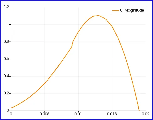
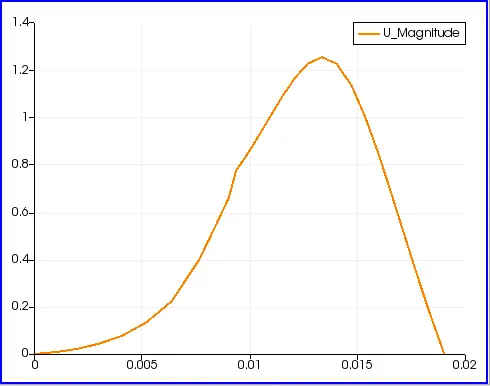
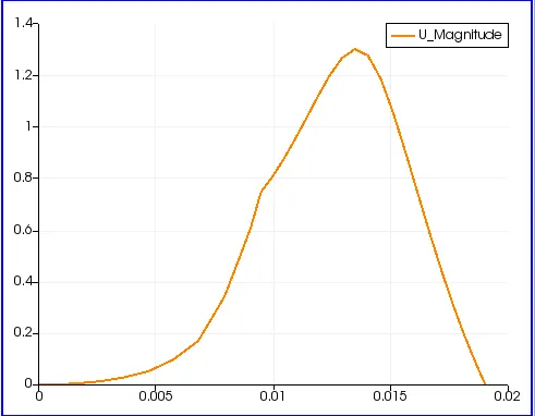
The obtained velocity profile is parabolic in nature. Due to shear force , velocity is nearly zero at wallsand at the centre of the pipe velocity is maximum .A slight increase in velocity at centre of the pipe which is greater than the maximum velocity is due to velocity boundary layer.
Run 2:
GF=0.5
mesh:
Velocity contour:
velocity profile:
Run 3:
GF=0.8
mesh:
velocity contour:
velocity profile:
conclusion:
Effect of grading factor on velocity contour and velocity profile
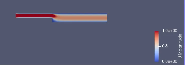
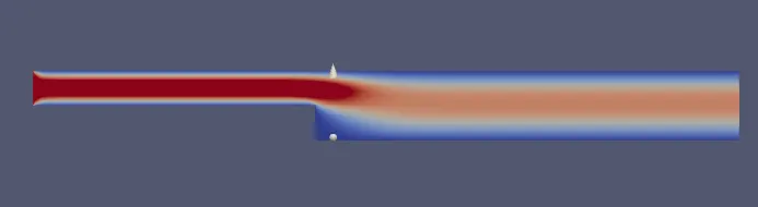
1) Increasing the grading factor leads to the coarser mesh inturn effect are seen in velocity contour where, contour becoming straight at step region. This is due to inaccurate information generated which leads to an approximation of solution rather than accuarte.
2) Coarser mesh leads to excitement of velocity at the center of the pipe which is greater than the predefined value.This effect continuous as mesh bcomes more coarser.
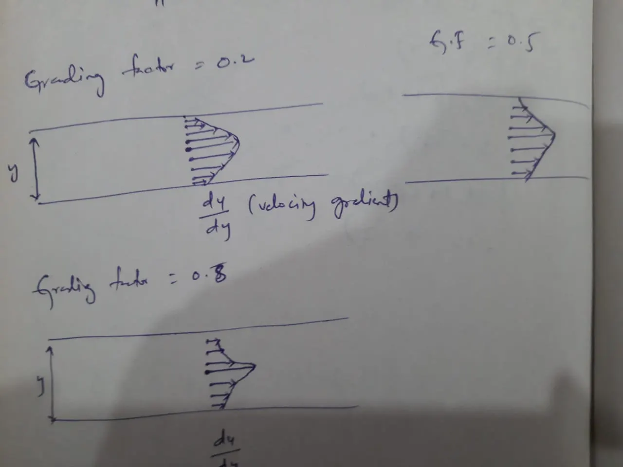
3)velocity gradient (du/dy) along y increases with coarser mesh , well explained in above figure.