Basic Morphing in ANSA
Objective:
Understand the applications and advantages of morphing in industries and demonstrate basic morphing for a component in ANSA.
Morphing:
Morphing means changing form or shape. Usually in a design cycle, FE modeling and simulations are performed once the concept CAD is generated. With the need to reduce design iterations, it will be useful if the concept changes are made in the FE model itself, taking the time required for CAD generation, off the cycle. This can be achieved by CAE Morphing. Morphing as the name suggests is an adaptation of given shape to a new form. The same concept is used in case of mesh morphing. In this method, the concept model or the donor model can be modified/altered to required proportions to create new designs using morphing techniques.
For instance, the solid or shell mesh of a structural part ready to be processed by an FEA solver, or the volume mesh complete with boundary conditions for a CFD solver, can take a new shape by just updating nodal positions. This means that the topology of the mesh (nodes count, cells count, connectivity) stays the same. Only the x,y,z coordinates of the nodes in the part of the model undergoing a shape modification are updated.
Mesh morphing can be used for different purposes: create shape parameters (i.e. change a length, an angle a thickness), move onto a new known shape (i.e. as manufactured, as designed by CAD), move onto a shape predicted by the CAE solution (automatic shape optimization with adjoint or BGM), and/or support multiphysics (move CFD mesh according to the evolution of the FEM-connected one, enable erosion/deposition).
Usually mesh morphing is faster than remeshing for a number of reasons: it avoids “remeshing noise” (having the same mesh adapted means the effect of a parameter is not confused with the effect of a new mesh structure), so variation effects can be assessed even with a coarser mesh. The CAE model can be updated on the background keeping all the original settings (boundary conditions). The update of nodal positions usually requires less computational efforts vs a full mesh regeneration. Creating shape parameters with mesh morphing is faster than creating a parametric CAD model.
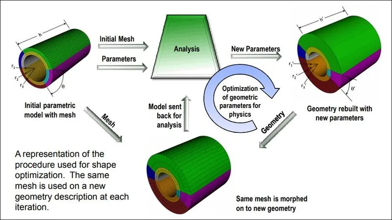
A typical design iteration process with morphing is explained in image below,
Benefits and applications:
- Component and full system level FE/CFD models (such as automotive vehicle Crash, NVH and durability models) can be morphed to fit target design features such as styling lines, sections, proportions etc. precisely.
- Minimizes time in design modification by directly working at mesh level thus improves the overall lead time
- Creation of ‘n’ number of parameters for different designs, enabling easy trial and error method of design correction
- For the cases where, parametric CAD is not available or is not easily linked to the CAE, morphing softwares allow engineers to study parameterized changes in the attributes of vehicle geometry.
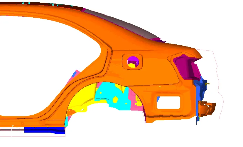
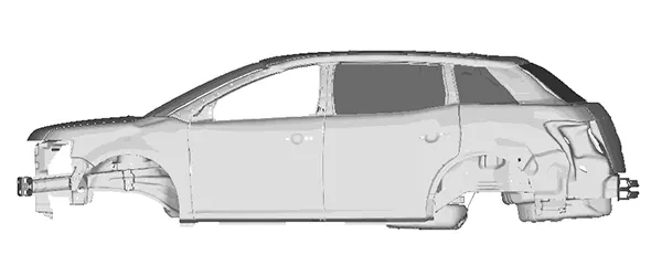
- In automatice industry morphing is commonly used for match styling, upper body to carry over under body matching, morphing sedan to station wagon or SUV etc. rapidly.
Procedure:
ANSA provides full fledged morphing tools that can be used to efficiently change shape of both FE and/or Geometry based models. Here, we are going to take a look at Box morphing method which is a very simple but powerful method to quickly make design changes.
First, the component is imported into ANSA. The component that will be morphed is shown in image below.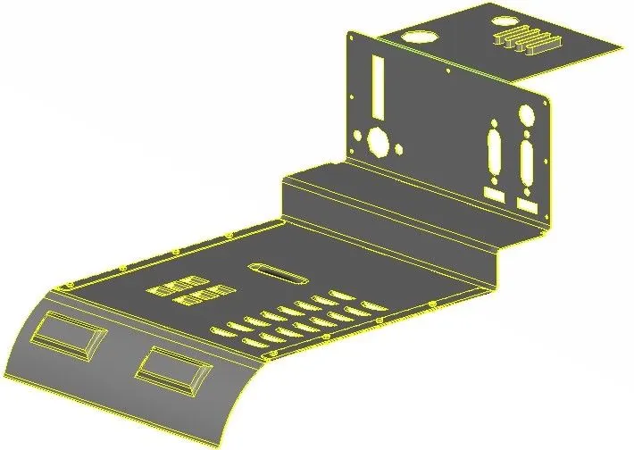
Note: All the changes that will be done for this geometry are arbitrary.
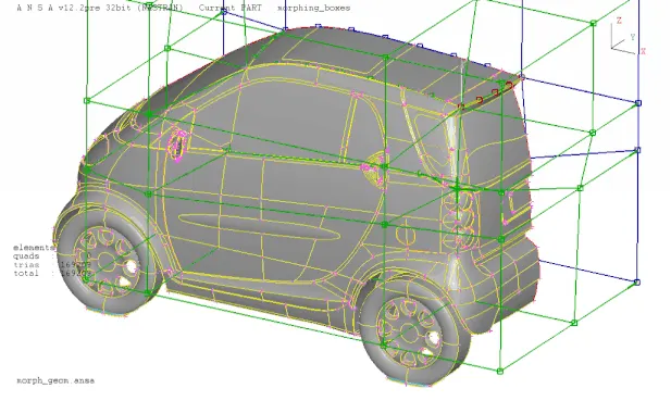
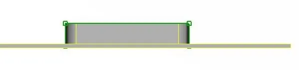
To perform morphing actions, switch to Morph module. There are lot of tools to perform any given task. For box morphing, we first need to create a box volume around the geometry that needs to be morphed. To do so, got to Boxes>New>Ortho and 'New morph' window pops-up. Here, we can select the type of entities that needs to be selected and morphed and the type of box. As we only have a geometry model, geometry is selected as the entity type and Ortho as the box type. Then select the geometry and cofirm selection, to create a morph box around it, as shown in image below for the elliptical features on top,
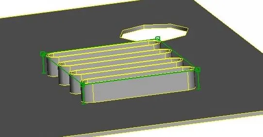
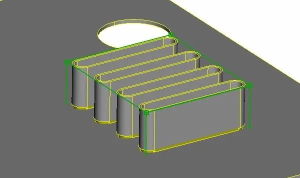
The box created has control points on its vertices, which are translated to change shape and size of the enclosed geometry. To translate the control points, go to Box morphing>move. Select the points that need to be translated and direction if required, then move the points freely in the specified directions. The image below shows the enclosed features height increased along the y-direction.
The morph box can also be split into multiple sections to have more control points and therefore more control over the geometrical changes. To split the morph box, go to Boxes>split. Split tools allows a lot of options to split the box, like user, project, parametric, number, etc. Select the appropriate option and click on the box to split. The image below shows a box volume split using number option both horizontally and vertically.
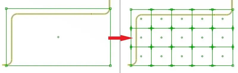
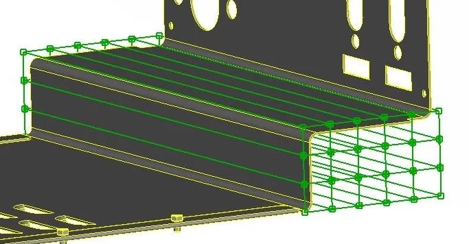
Again, the control points are selected and moved using the move tool to achieve the desired shape, as shown in the image below.
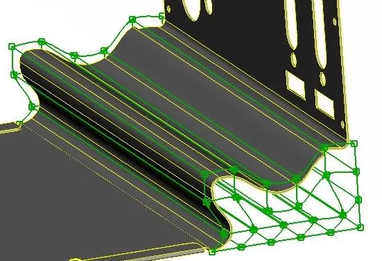
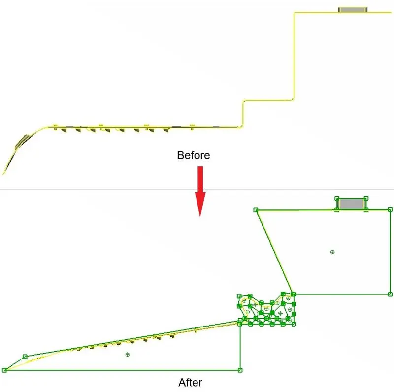
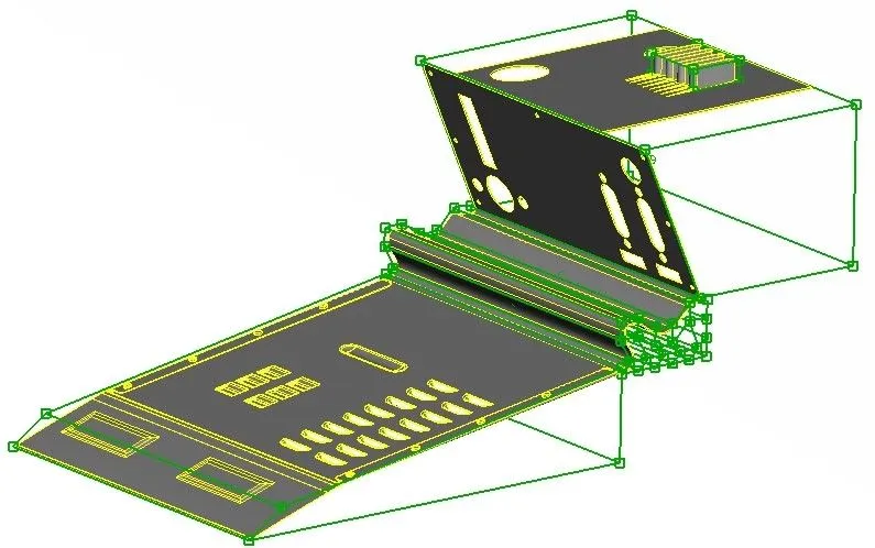
Similalry, some more changes are also made to the geometry. The final morphed geometry is shown below.
Conclusion:
Basic morphing for the component is done. We also learnt about the advantages and applications of morphing.
References:
https://www.designnews.com/design-hardware-software/mesh-morphing-explained
Google images