Meshing of car Backdoor in Hypermesh
Objective:
The objective of this project is to mesh the given 'Backdoor' of the car. The given 'Backdoor' model consists of a total of three different components. All the components of the hood need to have mid-surfaces extracted separately & then meshed according to the quality criteria given below. The target element length to be used is 5mm.
| S.N | Quality Criteria | Value |
| 1 | Aspect Ratio | 5 |
| 2 | Skewness | 45 |
| 3 | Warping | 15 |
| 4 | Taper | 0.5 |
| 5 | Min. Length | 3mm |
| 6 | Max. Length | 7mm |
| 7 | Min angle Quad | 45 |
| 8 | Max angle Quad | 135 |
| 9 | Min angle Tria | 30 |
| 10 | Max angle Tria | 110 |
| 11 | Tria % | 15 |
In this project, we will see the process of extracting midsurfaces manually for thin-walled components with complex shapes & features. For this purpose, we will be using Hypermesh software.
Procedure:
Following are the three components of the given backdoor model,
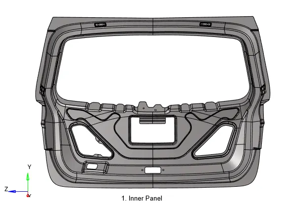
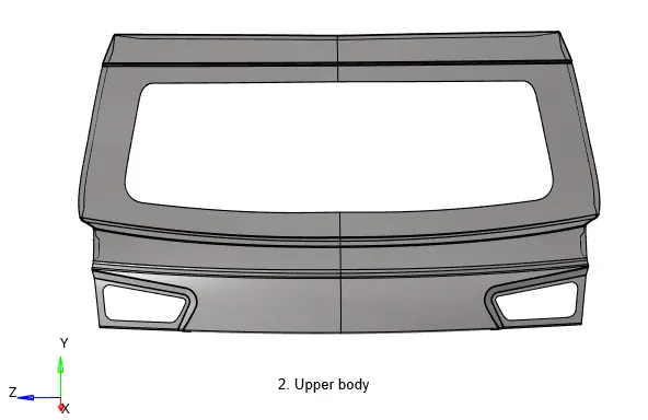
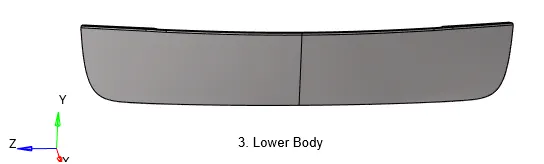
These are sheet metal components with a very small thickness. Therefore, it is suitable to create a 2D mesh for them. By doing so, the computational time and cost can be reduced significantly without affecting the final results. To create a 2D mesh, we need to extract the midsurface of all three components individually and then mesh the midsurfaces. After that, the thickness is assigned to the created mesh to capture the actual geometry.
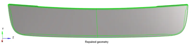
First, the given model is imported as geometry into the Hyperworks Optistruct workspace. After importing the model, it is important to properly understand the geometry of the model and clean up any errors like missing surfaces, duplicate surfaces, etc. There were some errors in the imported model like missing surfaces shown below in Lower_body.
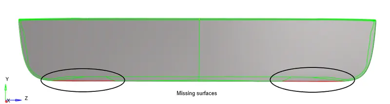
The free edge (red edge) shows that the geometry is not closed and the surface is missing there. To resolve this error, the nearby surface is split, deleted and then the whole surface is re-created using surface edit tools.
Similarly, there were some duplicate surfaces, which were deleted.
The next step is to extract the mid-surfaces for all the three components separately and assign thickness, property, and material to them. For Inner_panel, midsurface is extracted manually by offsetting the surfaces on one face. First, the thickness of the components is measured using the distance tool under the Geometry panel and was found to be 0.75mm. Next, midsurfaces are extracted by going to Geom>surface edit>offset and selecting all the surfaces on the inner face. Then selected surfaces were duplicated to an empty component. The offset value is set to 0.375mm. The same procedure is repeated for Upper_body. Upper_body is symmetrical, so midsurface is extracted for only one half.
For Lower_body, midsurface is extracted using the auto-midsurfacing tool. After extracting midsurfaces, they were checked for geometry errors. No errors were found.
Next, a material named Steel is created by right click>Create>Material in the model tree tab. Similarly, a property named Midsurface_mesh is created by right click>Create>Property. Under property configuration thickness (T) is assigned a value of .75mm. Card image & Material is set to PSHELL & Steel, respectively. Then, this newly created property is assigned to all the extracted midsurfaces, and material gets applied automatically.
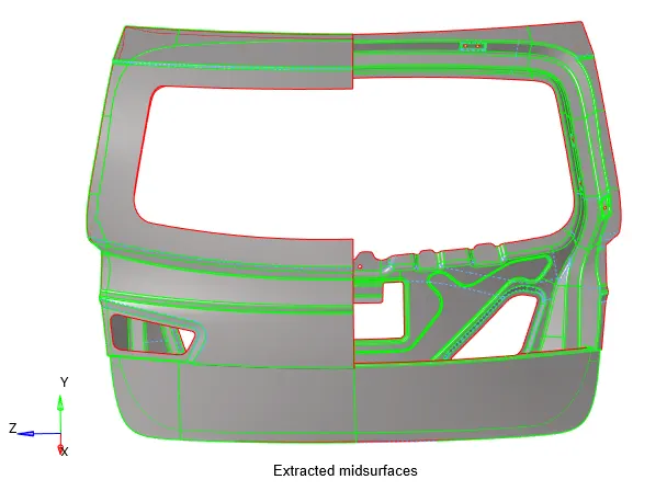
Before meshing, the midsurfaces were analyzed carefully, unnecessary edges were toggled & surfaces split into simpler and small sections such that mesh can be optimally controlled. The next part is meshing the midsurfaces. To create the mesh, automesh tool under the 2D tools panel is used. Element size is set to 5mm and mesh type is configured to mixed.
Here, we are assuming that this mesh will be used for crash analysis. From that perspective, it is important to ensure that there are only quad elements. Sometimes the shape of the surface itself is such that having only quad elements will introduce some rotational quad elements. For crash analysis, rotational quad elements are not at all suitable. In such cases, tria elements are preferred. And while dealing with the tria elements, it is important to ensure that there are no opposite trias and no back to back trias touching each other. Another thing to ensure is that the flow of mesh elements is consistent throughout as much as possible.
And most importantly all the elements must pass for the quality criteria. Quality criteria can be checked by going to Tool>check elems or 2D>qualityindex. There are a number of tools available under the 2D & Tool panel which are used to control the mesh quality. It also needs to be checked that there are no duplicate elements. Next, the mesh is checked for free edges to ensure there are no connectivity issues between the elements. Next, elements normal check is done, to ensure all the elements normal are in one direction.
Conclusion:
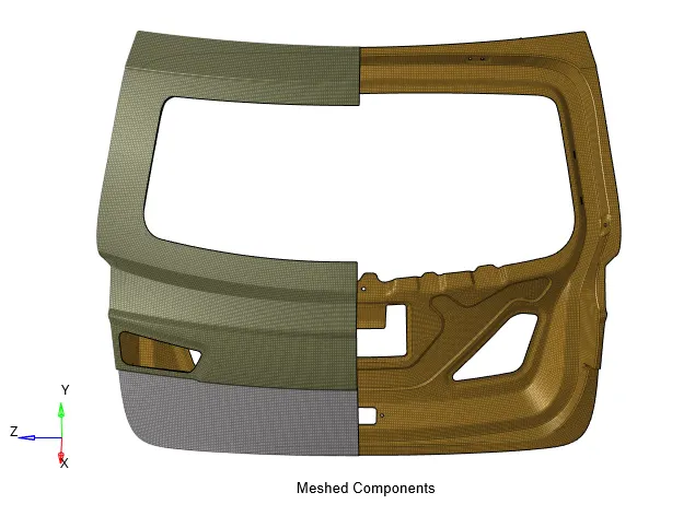
The 2D mesh is generated for the given backdoor components successfully as shown below, with a low tria concentration of 0.92%.
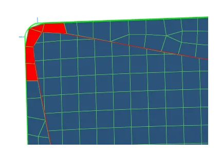
All the elements passed on the quality criteria except for a few regions in the Upper_body component, where it was not possible because of the geometry size/shape itself. Such as the following elements are failing for minimum length because the geometry itself is of small size and cannot have a bigger element.
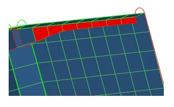
The mesh was also checked for free edges to ensure that there are no connectivity issues between the elements. Elements normal check also ensured that all elements normal were aligned properly.
Note: Please find the 26_Final.hm file attached.