Week 8-3D Tetra Meshing Challenge
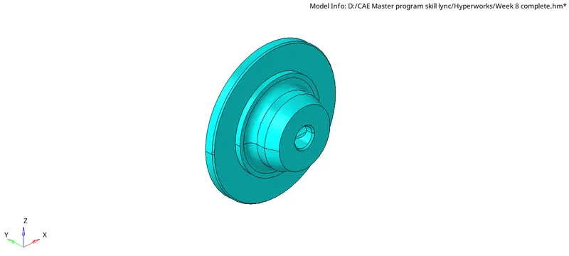
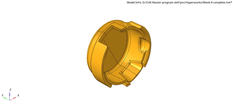
Housing model:
Objective ;
To create a Tetramesh for housing component by using Tetramesh generation method by converting the model from 2D to 3D with mentioned criteria
Procedure:
- Firstly import the geometry file from the system file.
- After importing the model delete the solid part of the component.
- Defeated the surface fillets with are having low fillet radius that may result in failure of elements.
- Prefer the geometry cleanup whenever it is required to get rid of failed elements.
- Go to 2D mesh panel- automation - select the preferred element size as 4MM.
- Select the Tetra elements as we have to generate the tetramers.
- Generate the mesh with the mentioned criteria after missing check the elements for quality check in tools- check elements panel- 2D.
- Do the quality check up for the minimum and maximum length.
- After college Jacob is denote done convert the model from 2DTria elements to 3D Tetra elements.
- Then go to the to 3D mesh – Tetra mesh on select the elements option that has to be converted from 2D Trai to 3D Tetra.
- Generate the 3D mesh of the components .
- After the treaty 3D mesh check the elements for the quality check-up in tools check elements- 3D for the Tet collapse,
- Do the quality check up for the tet collapse elements.
- And then for the failed tet collapse elements we have to do Tetra re-mesh we’re sending the Tetra mesh parameters in the Tetra mesh parameters panal.
- By preferring Tetra mesh we can get rid of the failed tet collapse elements.
- For the tetra remesh go to Tools-Tetramesh- tetramesh parameters.
- After that I think that Max Tetra on Min Tetra by checking the checkbox in Tetra mesh parameter panel.
- Under element quality target assign that tet collapse value under tick the check box off all voids,fix,mid-nodes and smoothing.
Result:
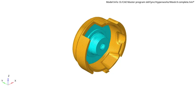
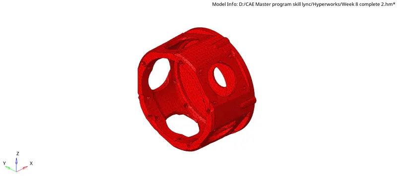
For the given housing component Tetra mesh is generated by converting 2D trai elements do 3D Tetra elements, the final model image is also as follows.
Learning outcome:
- Various techniques for creating the tetrtameshing.
- Understanding the 3Dmesh quality error and cleaning that.
Model-2:
Objective:
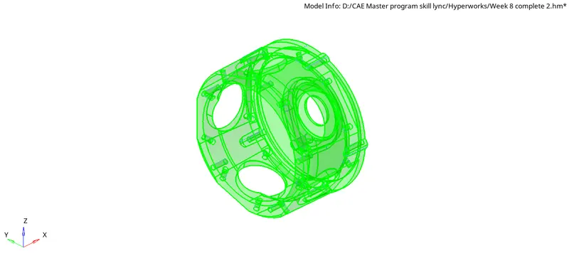
To create a 3D Tetra mesh by using quick Tetra mesh method for the given component with the mentioned quality criteria.
Procedure:
- Import the IG ES file from the system files.
- After importing the model create the solid parts of the component.
- Perform the geometry cleanup wherever it is required.
- For mashing the model use the quick Tetra mesh method we have go to the utility panel.
- For utility panel use view options. View- browsers- hypermesh- utility .
- After that select the Geom/Mesh from utility menu .
- Then select the quick Tetra mesh as it opens a panel named as quick Tetra panel.
- In that panel select the components to be measured and specify the mesh size minimum element size and change the mesh type to trias only.
- Click on the mesh options to generate the tatra mesh.
- After generating the Tetra mesh we need to check for the failed tet collapse elements.
- For checking the failed elements in quality criteria check up as tet collapse.
- Another method to improve the tet collapse value is by using the distance option.
- The element tet collapse is saved and go to mask option and selecting the ‘Ekements-retrieve-Now use mask and reverse the mask.
- Now we get the failure element for visible to us.
- Now use distance option for clearing the tet-collapse elements.
Conclusion:
- 3D mesh generating user the Quick tetra method.
- Performed 3D quality check and removed all the elements faillesd for tet-collapse.
Learning outcome:
- Understand the quick tetra mesh method.
- Clearing the tet-collapse elements.
Creating tetramesh for assembly components:-
OBJECTIVE:
- Mesh the components using quick and volume tetra meshing technique.
- Perform elements quality check on each of the components.
PROCEDURE:
- Import the 'assembly.hm' file from the import model tool.
- Take a moment to inspect the geometry. For the component we will convert the trias elements into tetras elements.
- In order to mesh the components with tria's we need to perform topology cleanup. Remove the surfaces where elements will fail for minimum length. Defeature all of the small surface fillets. Use toggling and replacing points options to clean the geometry.
- For component 1. use volume tetra meshing method. Access the tetramesh panel from 3D page.
- Go to the volume tetra subpanel. Set the entity selector to surface and select the surfaces in the model. Verify that 2D type is set to trias and 3D type is set to tetras. Specify '4' as the element size. Click mesh to generate the mesh.
- For rest of the components use quick tetra mesh method.
- Go to the 'View' option. Click on Browsers and then click on Hypermesh then an option for utility will appear. By selecting on it, access to geometry/mesh option will appear on panel. Select option 'Quick tetramesh' from mesh tools. Set the entity selector to surface and select the surfaces in the model. Specify '4' as the element size. Click mesh to generate the mesh.
- Access the check elements panel to eliminate the failing elements. Identify elements having a tet collapse value smaller than 0.15.
- We can rectify the failing elements by remeshing with tetramesh paramaters. Increasing the distance between nodes using distance tool can also fix the failing elements.
CONCLUSION:
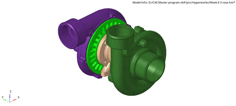
- Tetrahedral mesh generated using the volume tetra meshing technique.
- Remeshed with tetra parameters to achieve a better element quality.