Week 4-1D Element Creation Challenge
Aim: To create the 1D element on the given component.
OBJECTIVE: To mesh the given component with the size of 5 units. Create 1D element on the following component with the given cross-section and DOF
- Rod element:- Translational DOF should be Constrained with RBE2 link
Cross-Section: BOX- Dimension a= 12 mm
dimension b=10 mm
Thickness t= 0.75 mm
- Beam element:- All DOF should be constrained with RBE3 link
Cross-Section: I Section- Dimension a= 8 mm
Dimension b= 10 mm
Dimension c= 8.5 mm
Thickness t1= 0.75 mm
Thickness t2= .6 mm
Thickness t3= .6 mm
- Bar element:- Constrain only xand y DOFs With RBE3 link
Cross-section: X section- Dimension DIM1= 5 mm
Thickness DIM2= 1.2 mm
Dimension DIM3= 10 mm
Thickness DIM4= 1.2mm
- & e. Apply the massof magnitude 10 with the RBE2 link
- Join the two components with Spring elements
INTRODUCTION:
1D element are used for modelling line-type members such as columns, piers, beams or poles. 2D elements are commonly used for plate-type members such as walls, sabs, shells, bridges abutments, tanks, domes. 3D elements are used for structures with complex geometry which cannot be simplified for analysis.
While working with 1D elements we come across the following elements type:
- CROD
- CBAR
- CBEAM
CROD:
- CROD elements suppor (allow) tension and compression only. Also in certain software used for rotational as well but also limited
- The nodes of a CROD elements only have translation DOF(still this element has a torsional stiffness).
CBAR:
- CBARS elements support (allow) tension, compression and bending as well.
- A CBAR element is a kind of simplified CBEAM element and should be used whenever the cross-section of the structure and its properties is constant and symmetrical.
- The CBAR element requires that its shear centre and the neutral axis coincide. Due to this requirement CBAR elements are not useful for modelling structures that may warp, such as open channel-section
CBEAM:
- Cbeam elements supports (allow) tension, compression and bending as well.
THEORY:
PROJECT METHODOLOGY:
1.MID SURFACE:
- Auto mid surface has been used to extract the midsurface for this simple bracket.
- Components has been created and assigned to the particular mid surface
2.ASSIGN MATERIALS:
- Create material.
- Here I have created a material and assigned to steel.
3.ASSIGN PROPERTY:
- Create property.
- ENTER Thickness value & element type.
- Also assign this create property to the particular components & material.
4.WASHER SPLIT:
- Washer split is used to capture the mesh near the holes properly
- The washer split offset value is given to 5 units in the project
5.2D MESH:
- What this project auto mesh is being performed for the element target length of 5 units
6.1D ELEMENT:
- Some 1D elements used in this project are,
- PBAR
- PROD
- PBEAM
- RBE 2
- RBE 3
- As part of giving details I have deployed the 1D elements.
- To deploy bar, rod, beam elements hyper beam has been used.
- Where hyper beam is used to create a cross section
HYPERBEAM:
For the given data a. Rod element, B . Beam element, c. Bar element we will be created a cross section using hyper beam.
a.Rod element-(cross section-box):
- The given cross section details for the rod elements are,
- Cross section :Box
Dimension a= 12 mm
dimension b=10 mm
Thickness t= 0.75 mm
- To created this cross section Go to—1D—Hyper beam—Create—Standard section—Hypermesh—Thin walled box.
- The standard cross section shape will be created and enter the given dimensions
BEAM
B.BEAM ELEMENT-(I_Section):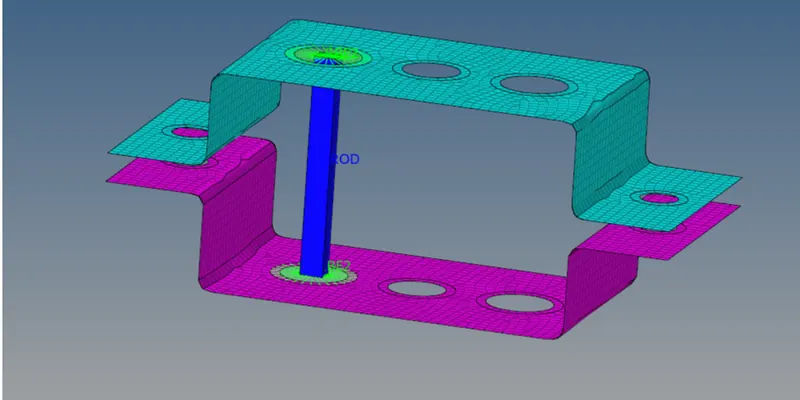
- But given cross section details for the beam element as per the given values
- To create the cross section go to, 1D—hyperbeam—create-- standard section—hypermesh-- I-section
- The standard cross section shape will be created and enter the given dimensions.
c.BAR ELEMENT (X-SECTION):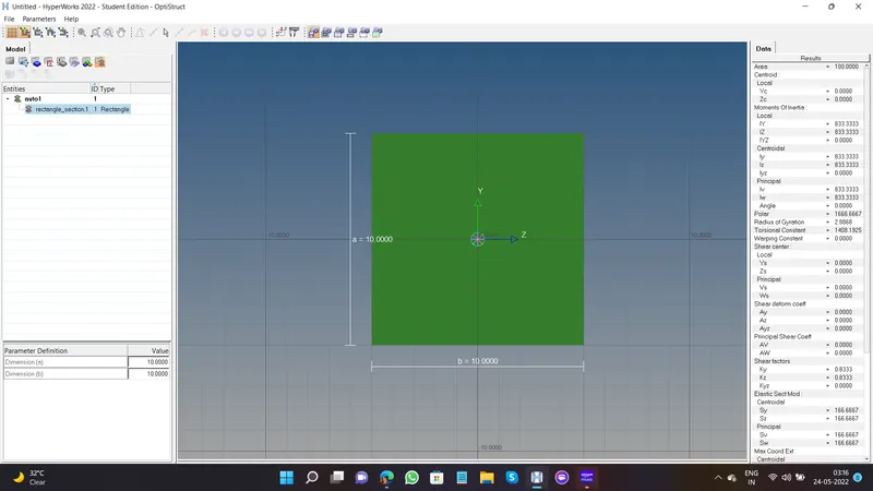
- Beginning cross section details according to the question
- Create the cross section go to-- 1D-- hyperbeam-- create-- standard section—Optistruct—CROSS
- The standard cross section ship will be created under the demolitions in the data.
Here, the cross section has been created for the bar, broad, beam element As for the given data. Now this cross section should be assigned to the particular property
CONCLUSION:
The mesh and cleared off one deal meant has been successfully assured as per the given input.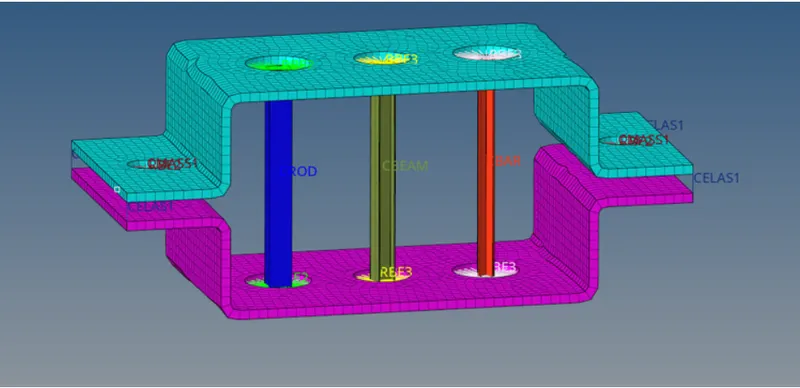
LEARNING OUTCOMES:
From this challenge, I can able to create 1D element as per the given inputs.