Week 8-3D Tetra Meshing Challenge
Aim:
To create a Tetramesh for the following given components with the following given quality criteria and tetramesh generation methods:
- Create a Teramesh for Housing component with the following quality criteria.
- TetraMesh Generation Method: 2D to 3D Conversion
- Elements sizes: Min- 2 Units, Target- 5 Units, Max- 7 Units
- Tet collapse: 0.15
- For the given model, Create a 3D Tetramesh with the following quality criteria.
- TetraMesh Generation Method: Quick Tetra Mesh/ Volume Tetra Mesh
- Target Element size: 3 Units.
- Tet Collapse: 0.15
- For the given assembly model, Create a 3D Tetramesh with the following quality criteria.
- TetraMesh Generation Method: Quick Tetra Mesh/ Volume Tetra Mesh
- Target Element size: 4 Units.
- Tet Collapse: 0.15
Procedure:
Model 1:
- The given model is opened in hyperworks using the Import geometry option
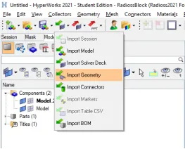
Figure 1 - Importing geometry
- The given model contains two components:
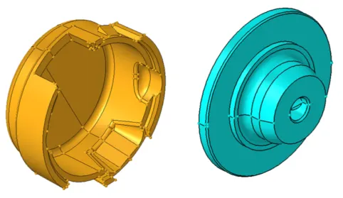
Figure 2 - Components in the given model
-
Geometry cleanup:
-
Select Geometry --> Autocleanup --> select Surfaces --> Enter target elem size parameters as “5” in parameters --> Enter the given quality criteria in criteria --> select Autocleanup
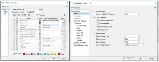
Figure 3 - Entering mesh parameters & quality criteria
The model after geometry cleanup is shown below: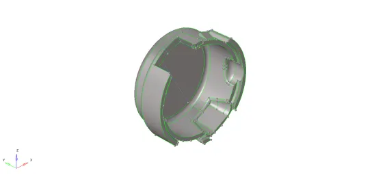
Figure 4 - After geometry cleanup
-
-
Meshing:
-
Select 2D --> Automesh --> Enter element size as 5 --> Mesh type as tria --> select the surfaces to mesh --> Select mesh
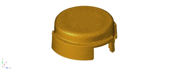
Figure 5 - Meshing of given model
By left or right clicking on the number on each edge of the model, the number of mesh points can be increased and decreased to achieve better mesh.
- Next, it is checked if the mesh generated passes the quality criteria. This is checked in the “quality index” option in 2D Tab. This is done as follows:
- The quality parameters entered during autocleanup is present in this option too. By toggling the “fail” option in display threshold, the failed elements are visualized

Figure 6 - Quality index toolbox
-
The elements are cleaned up by using one of the options in the cleanup tools. The tools available are
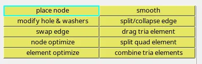
Figure 7 - Cleanup tools
- The final corrected 2D mesh for the component is as follows:
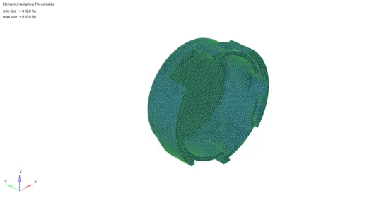
Figure 8 - Final mesh for the given model
- The quality parameters entered during autocleanup is present in this option too. By toggling the “fail” option in display threshold, the failed elements are visualized
-
-
Tetramesh generation:
-
Select 3D --> Tetramesh --> In fixed trias / quads to tetra mesh option, select elements --> displayed --> In tetramesh parameter, enter the tet collapse as 0.15 --> then in tetra mesh window, select “mesh”
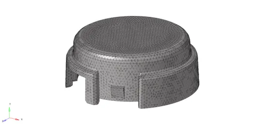
Figure 9 - Model after Tetra mesh generation
-
The quality check for the tetra mesh is done by using Tool --> check elems --> 3-d --> Enter 0.15 in tet collapse --> Select tet collapse. The number of elements that fail for the entered quality criteria are displayed in the left bottom of the screen
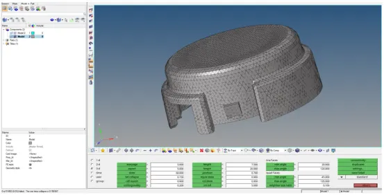
Figure 10 - Check elems option - Model
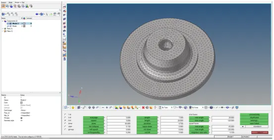
Figure 11 - Check elems option - Model 2
-
No elements failed for tet collapse. The final mesh of the given geometry is as follows:
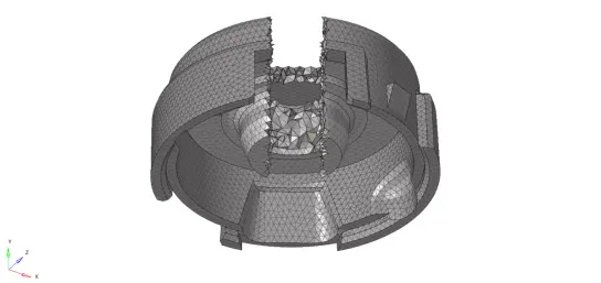
Figure 12 - Tetra mesh elements in final meshed component
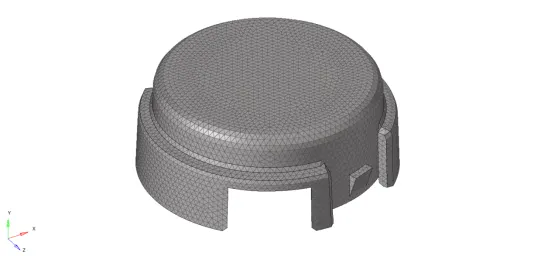
Figure 13 - Final meshed component
-
Model-2
- The given model is opened in hyperworks using the Import geometry option
Figure 14 - Importing geometry
- The given model contains only one component:
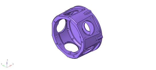
Figure 15 - Imported model
- The model is being meshed with Quick Tetra mesh method. Hence, the solid in the model is deleted using Delete --> Solids --> Displayed --> Delete entity
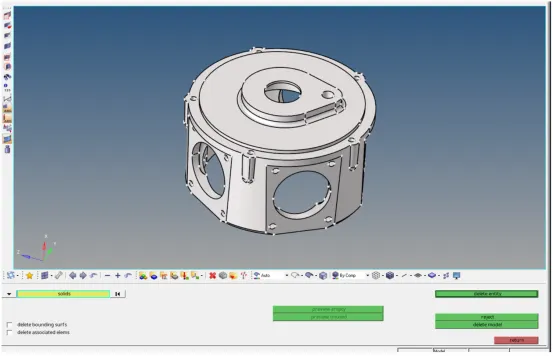
Figure 16 - Delete solids
After the solid is removed, the model contains only surfaces as shown below:
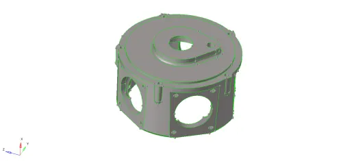
Figure 17 - Model with surfaces only
-
Meshing:
-
The mesh is created using Utility --> Geom/Mesh --> Quick tetra mesh --> Select components --> Enter mesh size as “3”, mesh type as “trias only” --> select mesh
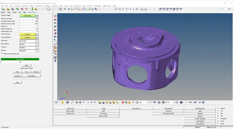
Figure 18 - Quick tetra mesh
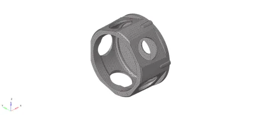
Figure 19 - Meshed component
-
The meshed elements are checked for the given quality criteria using Tool --> check elems --> Enter “0.15” in tet collapse and click on tet collapse option.

Figure 20 - Check failed elements
- The elements that fail are displayed in the bottom left of the screen. These failed elements are saved using the “save failed” option
-
To view these failed elements, press “F5” to open the mask option. Select elems --> retrieve --> mask --> reverse
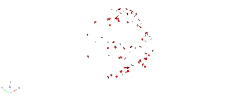
Figure 21 - Visualise the elements that fail for tet collapse
-
Select Unmask adjacent to reveal first layer of elements that are connected to the elements that fail for tet collapse
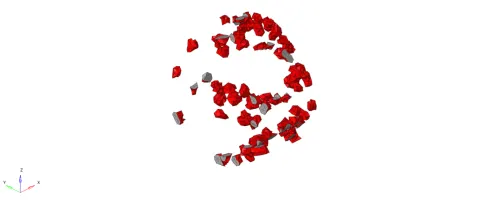
Figure 22 - Unmasking adjacent elements
-
These elements are remeshed using 3D --> tetramesh --> tetra remesh --> elements --> displayed --> Enter tet collapse as “0.15” in tetramesh parameters --> select mesh
-
Select unmask all to reveal all the elements of the mesh
-
The elements are checked for tet collapse failure using check elems. None of the elemens failed. The final mesh is shown below:
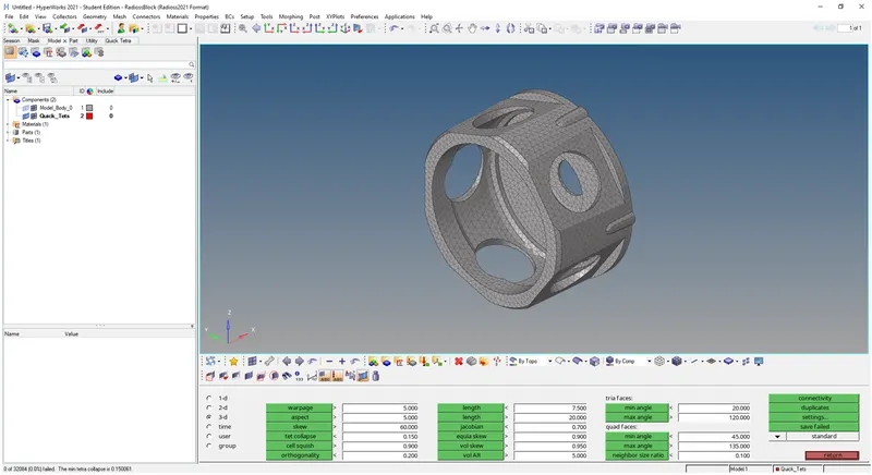
Figure 23 - Check for tet collapse
-
Model 3:
- The given model is opened in hyperworks using the Import geometry option
Figure 24 - Importing geometry
-
The given model contains five components:
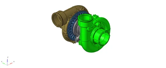
Figure 25 - Imported model
-
The fillets in the model were defeatured using Geometry --> defeature --> surface fillets --> enter the min & max radius --> select the surfaces --> select find --> select the fillets to remove --> remove
-
Three components in the model were meshed with Quick Tetra mesh method. Hence, the solid in the model is deleted using Delete --> Solids --> Displayed --> Delete entity. After the solid is removed, the model contains only surfaces as shown below:
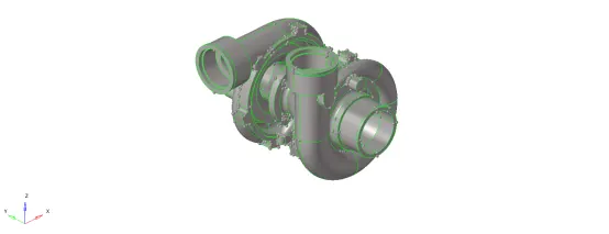
Figure 26 - Model after deleting solid
-
Meshing:
The mesh is created using Utility --> Geom/Mesh --> Quick tetra mesh --> Select components --> Enter mesh size as “4”, mesh type as “trias only” --> select mesh -
The elements are checked for tet collapse failure of 0.15. For which, the same steps discussed in Model 2 - Steps b) to h).
-
The other components in the model were meshed with Volume tetra mesh method.
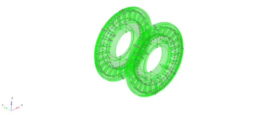
Figure 27 - Geometries with solid bodies
The steps for which is as follows: Select 3D --> Tetramesh --> select Volume tetra --> Select “solids” as enclosed volume --> select “displayed” --> Enter element size as “4” --> In tetramesh parameter, enter tet collapse as 0.15 --> select mesh. - The elements are to be checked for tet collapse. The same steps as discussed in Model 2 - Steps b) to h) is repeated
- The final mesh of the model is shown below:
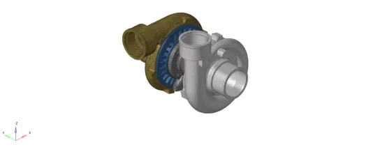
Figure 28 - Final meshed model
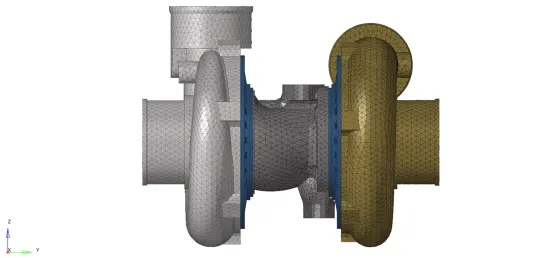
Figure 29 - Final meshed model
Learning Outcomes:
- Tetramesh generation for a component with 2D to 3D conversion and quick tetra mesh/ volume tetra mesh methodologies
- Correcting the components that fail for tet collapse
Conclusion:
The given three components have been meshed for the 3D meshing methods with the given target element size and tet collapse.