Week 8:- 3D Finishing - Challenges 1
1)What do you understand by the 3D finish process?
It is the process before sending the part for final simulation.The part should be checked for all proper clearences and representing the maching sides of a part by applying colour codes.In this process the part is checked with hole concentricity,designing of rough locators for guiding the panel.Fasteners are implemented as per the hole size & the standard color codes as per the customer requirement are applied to differentiate the type of hole,wheather its Dowel hole, threaded hole or Clearance hole.Renaming of the assembly & the part is done to give every part a different identity.
2)What are the points need to be taken care of while finishing the design?
- Hole concentricity & hole sizes- All parts Hole concentricity should be checked & confirmed for easy assembly while finishing the parts.
- Machining Area- The machining area in every part should be defined & the machining area should be highlighted by using standard color code.
- Nominality- All units dimensions shoild be maintained nominal to facilitate easy assembly of the unit.
- Holes colouring standard- Color Code standard as per the customer requirement should be applied in the 3D finishing.
- Pneumatic Layouting- pneumatic layouting is collection of different pneumatic pipes which works as a inlet to the pneumatic cylinder. It should be done properly for proper functioning of the units.
3)What are rough Locators & what is their use?
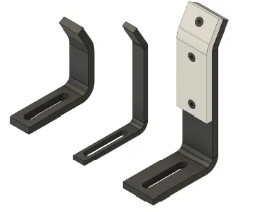
- A rough locator is a part designed to guide the operator, to locate the car panel on to the pins accordingly. A rough locator can be of standard part or make part.
- Rough locators are used to help locate workpieces in the automation process. Locating refers to the desired location where you want the workpiece to be when it is getting worked on either by a person, team, or robot.
4) What are the points you need to consider while designing a rough locator?
Following are the points need to be considered while designing the rough locator
- Rough locator should be placed at the edges of the car panel, which it has to guide.
- Rough locator has to be placed in the same angle of the car part edge with a minimum distance of 2-5 mm from the edge of the car part.
- Rough locator should guide the panel in pin arresting direction.
- Rough locator should start guiding the panel before 10 to 15mm to the start of the pin engagement.
- Rough locator should be designed with entry anglle for the car panel. Generally it ranges between 30-45 degree.
- Rough locator should be designed with two slots to mount the easy adjustments.
- The slots should be in the direction of car part guiding.
5)What is the gun study process?
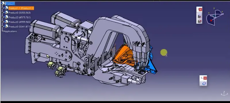
Welding is predominantely used in automobile industries and requirements for fixtures that ease the welding process is a continuous development task in any industry.Car Body-In-White (BIW) is a complicated steel-structure including 300~500 sheets with complex shape and are assembled by means of welding in a high rhythm through 55~75 robotic work-stations.The foremost step taken before starting the design of welding fixture is to arrive at the spot weld locations. The location and orientation of other critical units of the fixture including clamps, locators etc., are decided based on the weld spot distribution.
6)What are the points need to consider during the gun study?
- The axis of weld spot along welding direction must be normal to the weld surface.
- The no. of weld spots for the panel The time required to spot the each weld & the total time required to complete all the weld spots.
- If we have one or more Device models and we want to program; the behavior of each model in the work cell can be simulated over time. Instructions for each device are coded by giving Sequences. The sequence defines the motion, manipulation and action of the devices. Based on the distance of each tag point from home position, motion type, speed and acceleration – one can obtain cycle time for each device assigned with sequences.
- After sequencing all the devices, a simulation is run with "collision check" ON and made sure that the welding operation is collision free.
7) What is pneumatic routing?
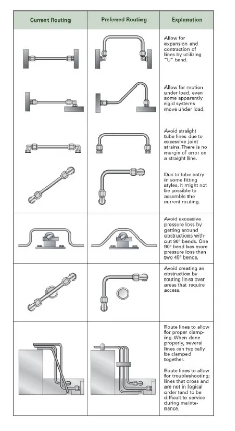
- Pneumatic systems should be efficient and leak free. Sometimes, they are not, because of improper tube line routing—the result of either lack of knowledge, or corners cut on planning time, or both.
- What can go wrong if routing is not done properly? All kinds of things! From not being able to access fittings for efficient maintenance all the way to leaking connections, inefficient or poor tube routing can create unintended issues that need to be addressed.
- planning tube line routing is a time investment, but it can have a big ROI—especially for complex systems. During system design, routing should be developed as the next step after sizing the tube lines and selecting the appropriate fittings.
8)What is the solenoid valve?
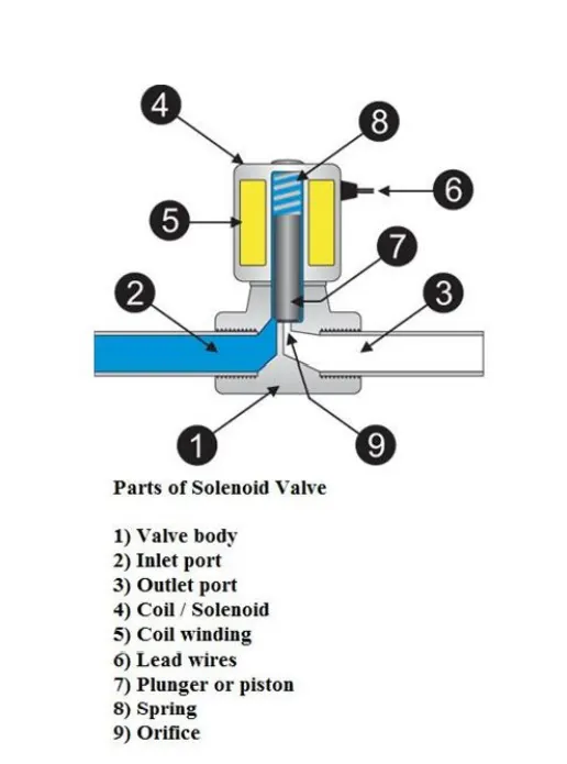
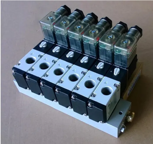
A solenoid valve is an electromechanically operated valve.Solenoid valves differ in the characteristics of the electric current they use, the strength of the magnetic field they generate, the mechanism they use to regulate the fluid, and the type and characteristics of fluid they control. The mechanism varies from linear action, plunger-type actuators to pivoted-armature actuators and rocker actuators. The valve can use a two-port design to regulate a flow or use a three or more port design to switch flows between ports. Multiple solenoid valves can be placed together on a manifold.Solenoid valves are the most frequently used control elements in fluidics. Their tasks are to shut off, release, dose, distribute or mix fluids. They are found in many application areas. Solenoids offer fast and safe switching, high reliability, long service life, good medium compatibility of the materials used, low control power and compact design.
9) What is the valve bank?
- Valve bank is the arrangement of no. of solenoid valves.
- Valve bank will have common inlet port, a single servo line to each of the pneumatic valves, and independent vent passages for each solenoid.
- On the solenoid bank, each of the solenoid valves separately controls the feed of high pressure servo air to a single pneumatic valve.
- The valve is actuated by selectively energizing the corresponding solenoid to allow servo air to the servo port of the valve. To return the valve to its fail-safe position, the solenoid is de-energized to vent the servo port of the valve to ambient.
- The solenoids are two-stage pilot valves and are normally open with the solenoid de-energized, allowing high pressure supply air to the servo ports of the downstream pneumatic valves.
10)What is sensor & brief about its application in automation?
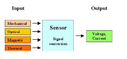
A device which detects or measures a physical property and records, indicates, or otherwise responds to it.n the broadest definition, a sensor is a device, module, machine, or subsystem whose purpose is to detect events or changes in its environment and send the information to other electronics, frequently a computer processor. A sensor is always used with other electronics.In the industrial automation, sensors play a vital part to make the products intellectual and exceptionally automatic. These permit one to detect, analyze, measure and process a variety of transformations like alteration in position,
length, height, exterior and dislocation that occurs in the Industrial manufacture sites.These sensors also play a pivotal role in predicting and preventing numerous potential proceedings, thus, catering to the requirements of many sensing applications.
11)What are the types of the sensor?
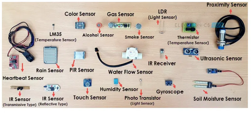
Temperature Sensor
Proximity Sensor
Accelerometer
IR Sensor (Infrared Sensor)
Pressure Sensor
Light Sensor
Ultrasonic Sensor
Smoke, Gas and Alcohol Sensor
Touch Sensor
Color Sensor
Humidity Sensor
Tilt Sensor
Flow and Level Sensor
12)What are the fundamental points that need to consider while designing or selection of sensor?
- Accuracy & Precision – These two terms do not mean the same thing, though they are often related. Accuracy has to do with how close the sensor reading is to the true value while Precision refers to the ability of the sensor to detect small changes.
- Environment – The selection of the proper sensor requires a good understanding of the environment in which the instrument will be operated. Many sensors can be affected by the non-ideal conditions of a production floor.
- Signal Conditioning – Electrical noise is always present, often more so on production floors, and can cause erroneous readings. Signal conditioners and other protection circuits can provide some protection from these effects before conversion.
- Processing – Even if signal conditioning is performed, the sensor and conversion process is full of various sources of error.
- Excitation – Many transducers require power to produce an output signal and it is important to provide a power source that will not introduce additional
errors.