Week 8:- 3D Finishing - Challenges 1
#1_3D Finishing:
It is the process where we complete the design entirely and prepare it for final simulation and Detailing.While finishing the design, the nominality of each unit and hole is checked to ensure that all units can be easily assembled. The concentricity and size of the holes should be checked to ensure that the various parts can be easily assembled. Fasteners are implemented based on hole size, and standard color codes based on customer requirements for differentiate type of hole/part. Standard hole colors are Sky blue for a simple hole, yellow for a threaded hole, cream for a machined area, and dark blue for a dowel pin hole. After completing all of the preceding steps, the model is sent for simulation and 2D detailing.
#2_Following points to be considered while 3D Finishing of Design Takes place:
- Machining Area
- Nominality
- Holes colouring standard
- Hole concentricity & hole sizes
- Gaps checking
- Pneumatic lay-outing
- Fasteners Implementation
- Avoiding Clashes between parts
- Mylars Spliting According to car panel surface.
- Proper Naming of parts/ assemblies as per standards.
#3_Rough Locators and its use:
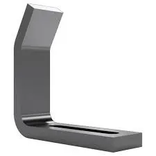
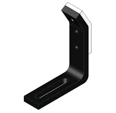
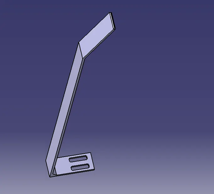
The rough locators are set according to the angle of the respective panel hence part can only be loaded in defined direction & orientation.
#4_Fundamentals of Rough Locator Designing:
- Rough locators should be placed at the car panel,which it has to guide.
- Rough locators should be placed in the same angleof the part edge with a min. distance of 2-5mm from the edge of car panel.
- Rough locators should guide in the pin arresting direction.
- Rough locators should start guiding the panel before 10-15mm to the start of pin engagement.
- Rough locators should be designed with entry anglefor car part entry.
- Rough locators should be designed with two slots to mount for easy adjustments.
- The slot should be in the direction of car part guiding.
#5_Gun Study
Gun study entails studying the weld gun, which is a portable equipment for semiautomatic welding of parts/components that will be utilised for the operation depending on the size of the part, thickness of the part, and so on. If the weld gun fall to the fixture unit then redesigning of that unit or the repositioning of that unit is done and again confirmed whether the gun is falling or not. Fixtures are redesignd if the gun falls to the fixture unit, the weld spot positions remains same.
#6_Various points to consider while Gun Study :
The total time required to complete all of the weld spots is determined by the number of weld spots on the panel and the time required to spot each weld. The weld spot's axis along the welding direction must be normal to the weld surface. If we have one or more device models and want to programme them, we can mimic the behaviour of each model in the work cell over time. Sequences are used to code instructions for each device.
The motion, manipulation, and operation of the devices are defined by the sequence. Cycle time for each device associated with sequences can be calculated based on the distance of each tag point from the home location, motion type, speed, and acceleration. The robot cycle time is properly computed in this manner. After all of the devices have been sequenced, a simulation is conducted with " collision check " enabled to ensure that the welding procedure is collision free.
#7_Pneumatic Routing:
Pneumatic systems should be leak-free and efficient. Sometimes they aren't because of incorrect tube line routing caused by either a lack of understanding or cutting cuts on planning time, or both. Planning tube line routing takes time, but it can pay off handsomely, especially in complicated systems. Routing should be developed as the next step in system design after sizing the tube line and selecting the necessary fittings.Routing should be designed with clamping in mind. Appropriate design logically leads to proper clamming. Several lines can frequently be clamped together. Consider troubleshooting and maintenance: focus on logical design and avoid crossed lines. Design the tube line routing to minimize the possibility of users standing or climbing on plumbing.
#8_Solenoid Valve:
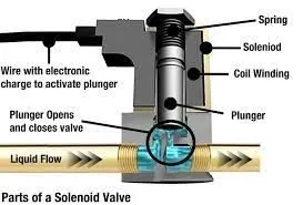
A solenoid valve is an electrically controlled valve. The valve features a solenoid, which is an electric coil with a movable ferromagnetic core (plunger) in its center. In the rest position, the plunger closes off a small orifice. An electric current through the coil creates a magnetic field.
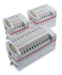
#9_Valve Bank:
The directional seated valves are available as chained valves in a valve bank. This facilitates the combination of different circuit symbols or actuation types in order to save space, and such systems can also be used to actuate independent consumers.
#10_Sensors:
A sensor is a device that detects and responds to some type of input from the physical environment. The specific input could be light, heat, motion, moisture, pressure, or any one of a great number of other environmental phenomena.
#11_Types of Sensors:
There are many different types of sensors, the main categories are;
- Position Sensors:There are many varieties of position sensor; linear, rotary, contacting, non-contacting and use a variety of different technologies. Position sensors are used to measure and monitor the position or displacement of an object.
- Pressure Sensors: Pressure sensors are often split into the following two categories; Pressure transducers and pressure switches. The main difference is that pressure transducers give accurate feedback on real-time pressure and pressure switches have a set limit which causes them to switch
- Temperature Sensors: Temperature sensors are used to measure and monitor temperature, whether this is the main variable requiring measuring or a secondary variable which requires monitoring as a safety precaution within another application.
- Force Sensors: They are used to measure various types of force, the main one being weight. Load cells are used in all types of scales; from bathroom scales to counting scales, industrial scales, truck scales, hopper scales and everything in between.
- Vibration Sensors: A vibration sensor is a device that measures the amount and frequency of vibration in a given system, machine, or piece of equipment. Those measurements can be used to detect imbalances or other issues in the asset and predict future breakdowns.
- Piezo Sensors: A piezoelectric sensor is a device that uses the piezoelectric effect to measure changes in pressure, acceleration, temperature, strain, or force by converting them to an electric charge.
- Fluid Property Sensors: Relying on tuning fork technology, the sensor monitors the direct and dynamic relationship between multiple physical properties to determine the quality, condition and contaminant loading of fluids such as engine oil, fuel, transmission and brake fluid, hydraulic and gear oils, refrigerants and solvents.
- Humidity Sensors: Humidity sensors work by detecting changes that alter electrical currents or temperature in the air.
- Strain gauges: A strain gauge is a type of electrical sensor. It's primary use is to measure force or strain. The resistance of a strain gauge changes when force is applied and this change will give a different electrical output.
- Photo Optic Sensors: Photoelectric Sensors detect objects, changes in surface conditions, and other items through a variety of optical properties.
- Flow and Level Switches: Flow switches are used to monitor and control the flow rate of fluid within an industrial process system. A level switch is an electrical or mechanical method for measuring the level of a liquid, powder, or granule material.
#12_Basic Fundamentals to design sensor unit:
- Every single loose panel which are being welded in tool should be sensed.
- Each panel Should be sensed 1 or 2 sensors depending on the siize of panel, preferred to be in diagonal opposite ends of panel.
- Every sensor shoould be mounted in all 3 direction adjustable way in general.