Fender Design Challenge
| Fender Design |
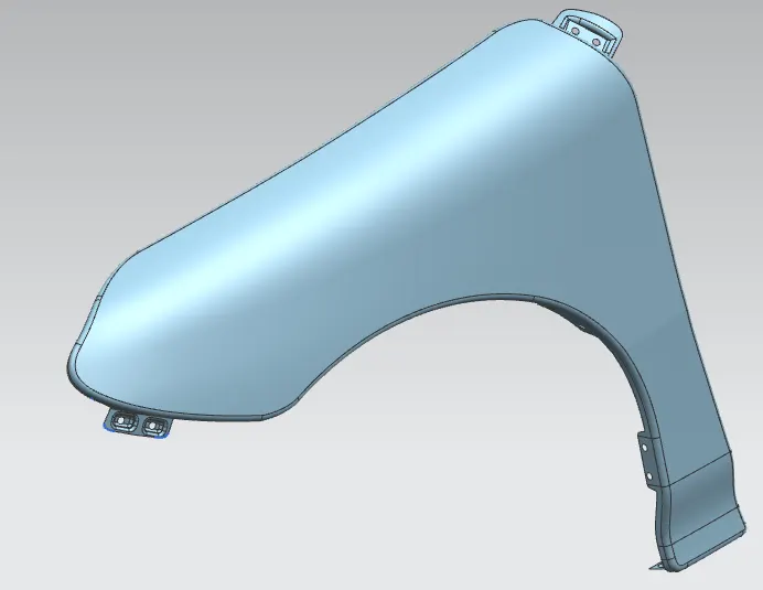
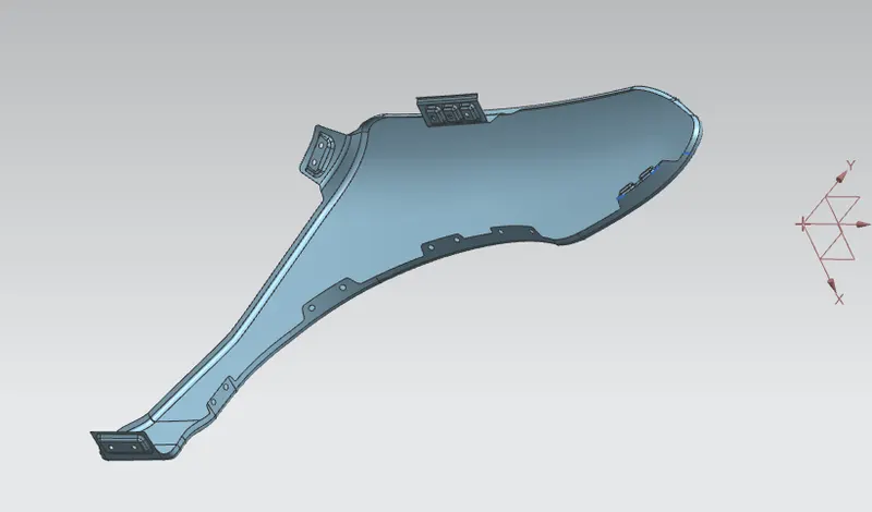
#Objective: To design Fender and the main design requirements Drip Area, Bumper, A-pillar, and Sill mounting Areas using the master section as a reference.
#Introduction: A fender is the curved portion of the car’s body that sits over and houses the wheels.
Its purpose is to keep mud, rocks, and other road debris from being thrown around by the tires. In other words, the fender is a housing for the wheels that keeps road debris contained. If nothing was covering the wheels, all kinds of debris would be kicked up by the rotating tires. The fender not only protects your car from sustaining damage from road debris but it prevents this debris from being thrown up at other vehicles on the road.
#Types of Fenders:
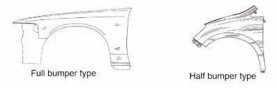
#Main Areas to be considered while designing a fender:
- DRIP AREA
- SILL MOUNTING AREA
- A PILLAR MOUNTING AREA
- BUMPER MOUNTING AREA
- BAFFLE MOUNTING AREA
1. Drip Area:
It is the area through which the fender is attached to engine housing through fasteners. There should be some consideration followed to design the drip area of the fender. From the backside of the front fender, there will be 200mm clearance for the cowl(wiper motor) mounting area.
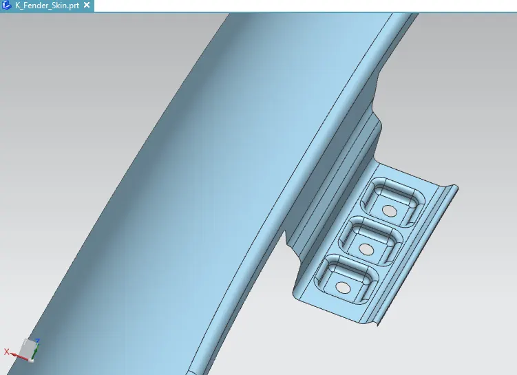
- Law Extensions according to the given data.
- Emboss creation of depth 4mm and Draft angle for #3 Parallelograms of 14 X 14 mm.
- Trim Sheet Hole of Diameter 5mm.
- Edge blend And Face blends of radius 2mm.
2. Sill Mounting Area:
It is the bottom area of the fender. It gets connected with the door region of the car.
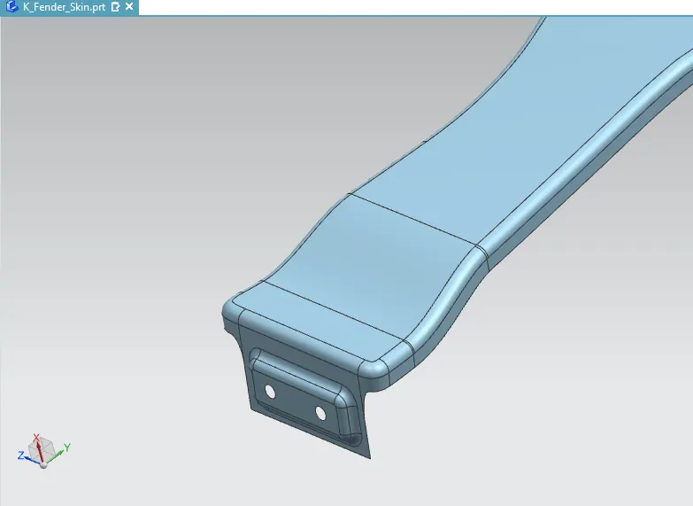
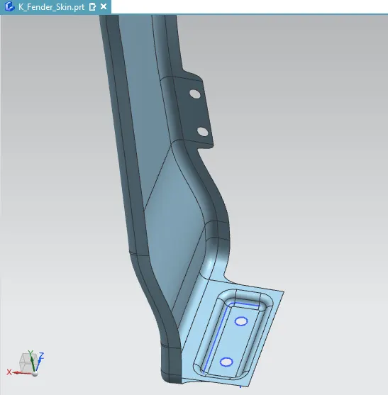
- Extend Sheet up to 15mm.
- Emboss A rectangle of 45 X 16 mm and depth 4mm.
- Trim Sheet #2 Holes of Diameter 5mm.
- Edge blend and face blend of radius 3mm.
3. A-Pillar Mounting Area:
This mounting area is located near the cowl top of the car, where it is fastened with the cowl.
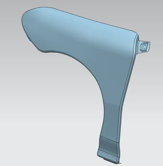
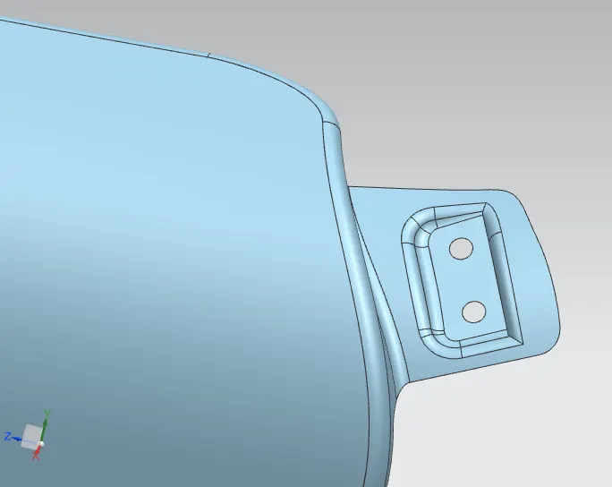
- Used law extension to extend sheet up to 42mm.
- Used Trim Sheet to remove unwanted material.
- Use of Curve on surface to create the sketch for mounting.
- Trim Sheet for creating holes of diameter 5mm.
4. Bumper Mounting Area:
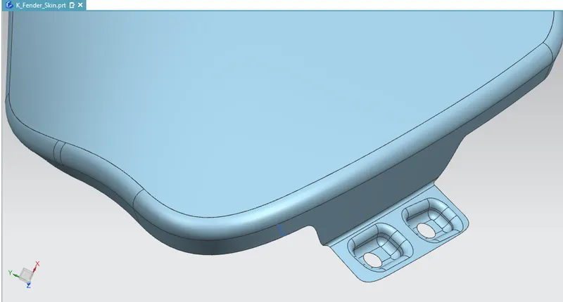
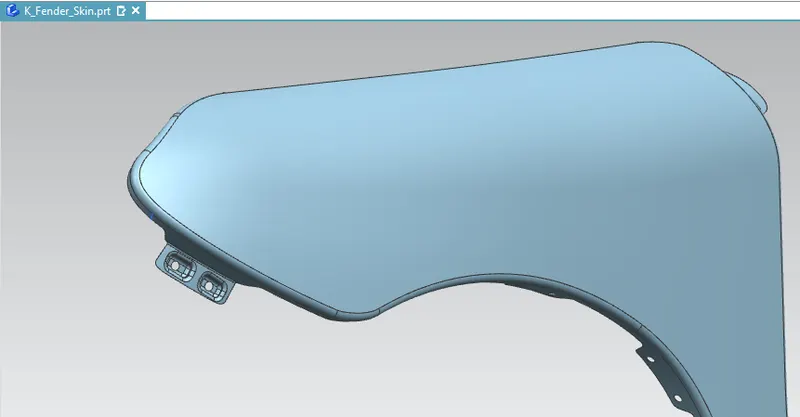
- Used Law Extension of 15mm length at an angle of 75 degrees.
- Used Bridge curve to remove sharp corners.
- Embossed sketches at the draft angle of 15 degrees.
- Used Trim Sheet to create #2 holes of diameter 5mm.
5. Baffle Mounting Area:
In this mounting area, baffles are mounted using fasteners, which are used to seal the opening between the wheel & engine compartment.
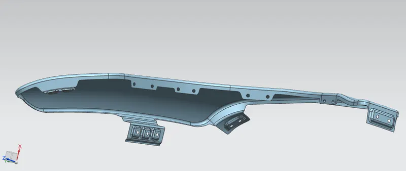
#Conclusion: Hence, The Fender design has been completed successfully And I have grabbed knowledge about certain commands in NX Cad Software through this Challenge.
I have attached the Part file of the Fender design for Evaluation.