Week 8:- 3D Finishing - Challenges 1
1.What do understand by the 3d finesh process ?
Ans:-
- 3D finish is a process where the design is being completely finish & to be ready for final simulation & 2D detailing .
- While finishing the design the normality of holes is cheacked which ensure the easy assembly of all the units.
- The hole concentricity & holes siz are cheacked which ensures the eassy assembly of different parts.
- The gaps between the different units checked to ensure the proper individual wowrking of different units.
- fasateners are implemented as per the hole size & the standard color codes as per the customer requirement are applied to differentiate the type of hole whether its a simple hole , threaded hole or counterbore hole .
- Renaming of the assembly & the part is done to given every part a different identify in which assembly part is going to be fit .
- After doing all these things the model is sent for simulation & 2D detailing .
2.What are the point need to be taken care of while finishing the design ?
Ans :-
Following points are taken into consideration while finishing the design
- Hole concentricity & hole sizes
All parts holes concentricity & hole size are checked for easy assembly while finishing the parts.
- Machining area.
The machining area in every part should be defined & the machining area should be highlighted by using standard color code . machining is to be done on the parts to properly mount with color code . machining only on desired faces reduces cost & save timing also machining increses accuracy of dimensions.
so before going to simulation or detailing machining area should be defined
- Nominality
All units dimension should be maintained nominal to facilitate easy assembly of the unit.
- Holes coloring standard
In 3D finish hole coloring should be done becouse it help to identify what type of hole it is ? it depends on cutomer standard specifies color like
Dowel hole should be given blue color .
Thread hole should be colored with yellow.
C. bore or open should be given blue color .
- Pneumatic lay-outing
Pneumatic layouting is collection of different pneumatic pipes which works as a inlet the pneumatics cylinder . it should be done properly for proper functioning of the units
- Gapes checking :
The gaps between the different units checked to ensure the proper individual working of diferent units .
Fasteners implementaion
fasterners should be implemented in all unit as per the requirement & load on the part
- Mylor splitting as per panel profile
mylor splitting as per panel profile should be confirmed while finishing the design.
Proper renaming of parts/ assembly as per the standard
Proper renaming of parts & assembly should be done while finishing the design we can identify each & every part easily with unique idendification
3.What are rough loactor & what is their use ?
Ans:-
- Rough locator are usually used in loading & unloading of particular part.
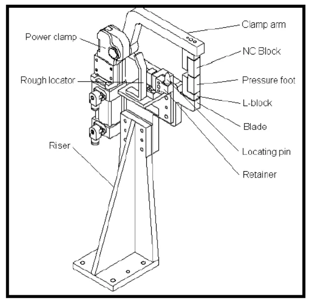
- Rough loactor unit is part designed to guide the operator loactor car panel on the pins accordingly .The have slot for adjustment. Rough locator to help loacate work pieces in the automation process locating refers to the desired location where you want the workpiece to be when it is getting working on either by a persons , team or robot . The accuracy of loacting components direclty the consistency & how final product will comes out .
- A rough locator can be of std. part or make part . it is also work as poke yoka.
- it can be called as fool proofing method also becouse due to the rough loacotor the part cannot be loaded in incorrect position . the rough loacotors are according to the angle of respective panel hence part can be loaded define direction & orientation .
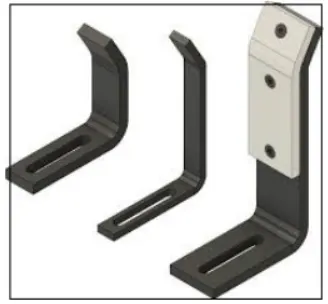
Rough locator can be directly mounted on base plate or combined with pin clamp unit as shown in below figure
4.What are the points you need to consider while designing a rough locator?
Ans:
The point you need to considered while designing a rough loacator
- The height of rough loacators should not be more than the permissible ergo height of the fixiutre.
- the entry point / yop point of the rough loactor must be 10mm-15mm above the panel surface .
- Rough loacator should have adjustment in the direction of the guiding plane.
- 2mm gap to be maintained between rough loactor and panel at the time of design and we can provide adjustment of 5-10mm in the positive or negative direction of guide plane .
- Rough locator can be rod type or flate type , depending upon the standards and other conditions
5.what is the gun study process?
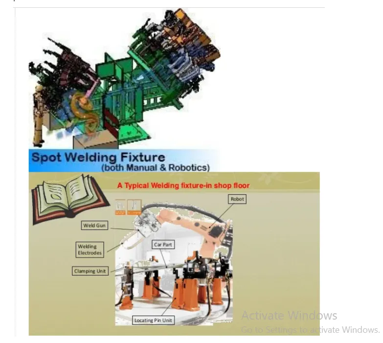
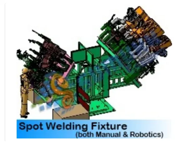
Gun study is the process of checking whether the gun is able to weld the selected car panels . The below image shown the gun spot welding and the weld loaction where the spot is created on the car panel . gun study is necessary as the BIW car panels are complex in share and sixe . in 3d software , the gun study is done by actually introduction a welding gun in fixture that we have designed . a according to that unit are designed . according to that unit are designed so that there's no problem while the welding prorcess
6.What are the points that need to consider during the gun study?
- The axis of weld spot along weld direction must be normal to the weld surface
- total no. of weld spot and time required for each is calculated for knowing the total time required for welding that car panel .
- Robot cycle time is calculated while doing the proper gun study
- collision checking is done without any collision with any units in the fixture.
7.What is pnematic routing ?
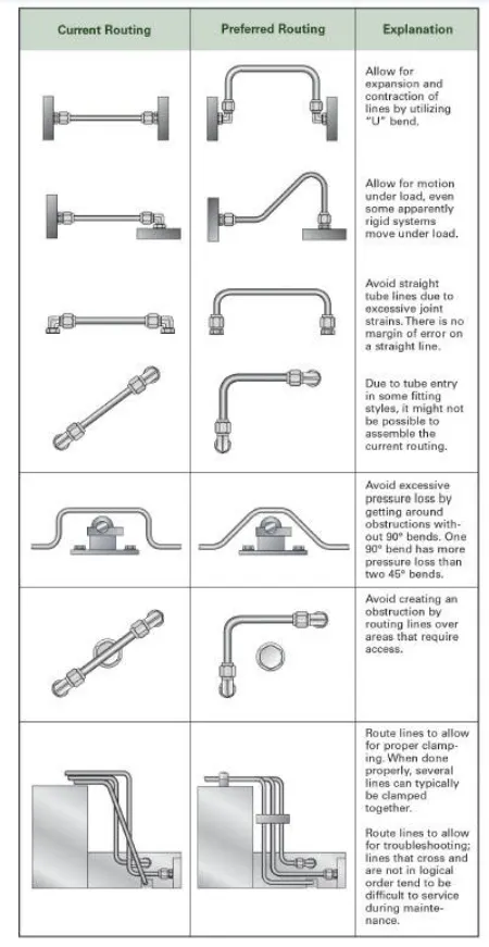
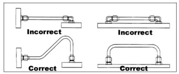
Pneumatic routing a planning tube lines route properly , leak-proof efficient working of pneimatic devices in a fixture like cylinder , solenoid , etc.
8.What is solenoid valve?
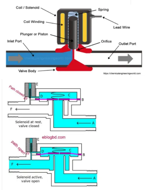
Solenoid valves are used to actuate the airflow in cylinder as per the sequence through a manual or PLC - operated system . it is a mechanical device used to control or regulate the flow of fluid.
components of the solenoid valve are as shown below.
9.Valve banks are basically a system in which a number of solenoid valves are mounted in order to maintain one common inlet and outlet of air to all the valves.
valves blank are mostly mounted on the fixure sides or the base plate depending upon the various conditions

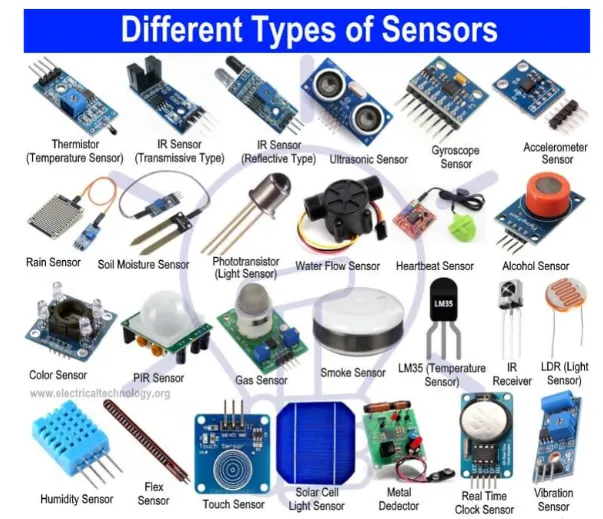
10. A Sensor is a device that produces an output signal for the purpose of sensing of a physical phenomenon . in the broadest , a sensor is a device module , machine , or subsystem that detects events or changes in its environment and sends the information to other electronics, frequently a computer processor.
Application:
1.To check the presence of car panel
2.To detect the position of the sliding unit .
3.When there is no, of similar car panel weld on some fixture sensors are used to detect car panel place in fixutre.
11.Type of sensor :- The following is list of different types of sensor the are commonly used in varous applications. all these sensor are used for measuring one of the phyical properties like temperature , resistance ,capacitance , conduction , heat tranfer , etc
- Temperature sensor
- proximity sensor
- accelerometer
- IR Sensor (infrared sensor)
- pressure sensor
- ligth sensor
- ultrasonic sensor
- smoke , gas and alcohol sensor
- Touch Sensor
- Humidity sensor
- Title sensor
- flow and level sensor
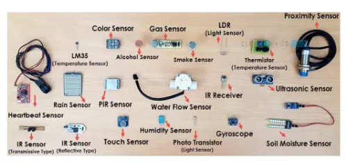
Some of them are described below
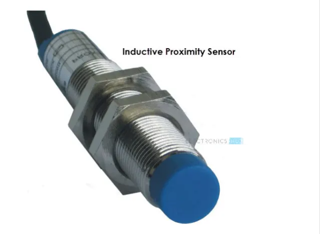
A)Proxitmity sensor Proximity sensor is non- contact type sensor that detects the presence of an object proximity sensor can be implemented using different techniques like optical(like infrared or laser), ultrasonic , hall effect , capacitive , etc.
12)What are the fundamental points that need to consider while designing or selecting the sensor?
Basic fundamental for sensor unit design:
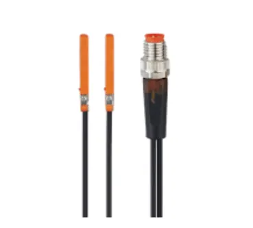
- A sensor unit is a unit designed to sensor the car panel by using electrical sensors.
- The signal from sensor will be fed to the PLC and the next process or not.
- It helps to avoid human error.
- Basically , sensor should be equally number as cameras to number of panel in an assembly . for (Ex. if 9 panels are in assembly , so there should be at least 9 sensor used)
- sensor should be slot is designed in such a way that can be adjusted in 3 directions.
- sensor are also used for the safety purposes of the operator.
- Typically proximity , LASER , Photelectric sensor are used in fixtures.
- some major sensor manufacturers are ifm pepperi-fuchs , sick, omron, etc