Week 8:- 3D Finishing - Challenges 1
1. What do you understand by the 3D finish process?
Ans:
- 3d finsihing is the final step of modelling of the fixture in which we complete all the necessary designs and nominalising the entire design.
- After the finishing of design the next step will 2d detaling thus if the finshing is done thouroghly then there will less error in 2d detailing and faster project compeletion.
- While 3d finishing we check several aspects like hole concentricity and snap each other part properly.
- We check the nominality of position of hole by refering to one edge and make every unit dimensions nominal.
- We also give severla color coding for the holes like for dowell holes the color is blue and for the screw entry hole the color is ceana
- For the threaded holes and machined surafces the color code is yellow and maroon respectively.
- For some components we give fillet radius to ensure the weldability.
- We also check with gun study and make further changes while nominalising the design.
- We add the necessary components like rough locators,valve box and check with the phneumatic routing.
2. What are the points need to be taken care of while finishing the design?
Ans:
Following points need to be taken care while finishing your design:
1. Hole concentricity & hole sizes
2. Machining area
3. Nominality
4. Holes colouring standard
5. Pneumatic lay-outing
6. Gaps checking
7. Fasteners implementation
8. Avoiding clash between different parts
9. Mylars Splitting as per panel profile
10. Proper renaming of parts/assemblies as per the standard.
3. What are rough Locators & what is their use?
Ans:
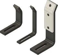
ROUGH LOCATORS
- Rough locators are basically used where manual loading of panels are to implemented on the fixture.
- These are used to guide the panels in correct position & orientation.
- These also help for proper Poka -Yoke.
- Materials used for rough locators are MS or similar metal.
4. What are the points you need to consider while designing a rough locator?
Following points need to be considered while designing the rough locators, Height of rough locators should not be more than the permissible ergo height of the fixture:
- The entry point/ top point of the rough locator must be 10mm-15mm above the panel surface.
- Rough locators should have adjustment in the direction of guiding plane.
- 2 mm gap to be maintained between rough locator and panel at the time of design & we can provide adjustment of 5-10 mm in the positive or ne ative direction of guide plane.
- Rough locators can be rod type or flat type, depending upon the standards and other conditions.
5. What is a gun study process?
An:
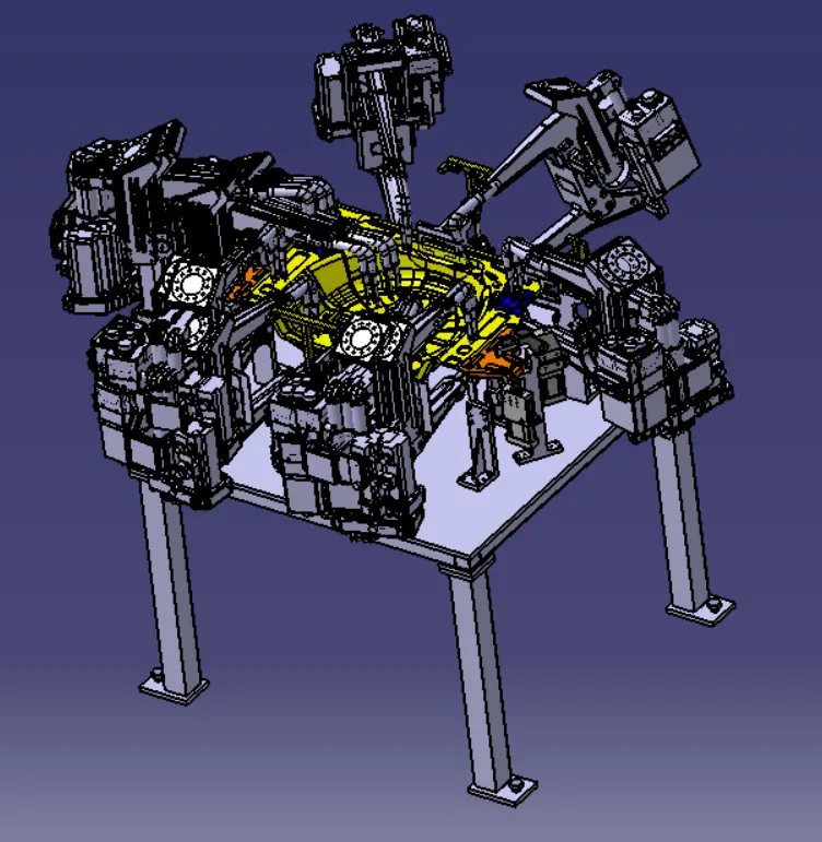
As shown inthe above pitcure the gun study is a process where we check the ease of welding of weld spots by ensuring the proper space adjustment for the welding gun to pass and do its work properly without damaging the component or clashing with other components.
6. What re the points need to consider during the gun study?
Ans:
- In the gun study we ensure that the proper space available for gun pass between the units and also retractable.
- We check weather the gun is not clashing with other parts
- Each and every spot weld is to inspected while performing the gun study
- Even after the 3d finishing a gun study is performed cause there might be clash since the units modified to a nominalised positions.
- Adjust the weld gun height and the concentricity to the weld spot so that we can have a precise observation.
- The bundle of the gun clouds compressed together is a called as gun cloud.
7. What is pneumatic routing?
Ans:
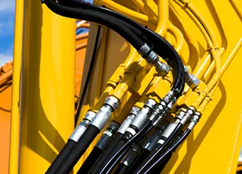
Pneumatic system or System operated with Air.
Open loop system.
- Generally used for low pressure.
- Generally delivers less force compared to hydraulic system.
- Cheaper compared to hydraulic for basic cost. But compressor running cost is more.
1. Pneumatic system is mostly preferred over hydraulic system in BIW welding fixture.
2. All toggle clamp, pin cylinder, slides are operated via pneumatic. Generally cylinder are designed to operate max pressure 12-13 bar.
3. As it expensive and difficult to maintain 10-12 bar in shop floor it is preferred to do design pneumatic systems at 6 bar pressure
4. Proper Pneumatic lay-outing or routing is very much important to be shown in design, as it helps in describing the best possible way to keep all pneumatic pipes neat & away from welding spatters which can cause wear or tear of pneumatic pipes.
5. In pneumatic lay-outing all pipes from cylinders are shown connected to valve banks and passes through a safety box like structure.
6. Various major suppliers for pneumatics items are SMC, Teunkers, Festo, CKD etc
8. What is the solenoid valve?
Ans:
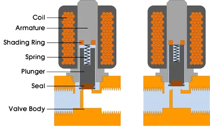
Solenoid valves are used to actuate the air flow in cylinders as per the sequence through manual or PLC operated system.
9. What is the valve bank?
Ans:
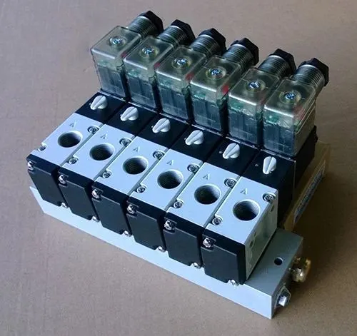
- Valve Banks are basically a system in which n numbers of solenoid valves are mounted, in order to maintain one common inlet & outlet of air to all the valves.
- Valve banks are mostly mounted on the fixture sides or on the base plate depending upon the various conditions.
- Example: If we 4 operating sequences in one process of cylinder, this means we will be using 4 solenoid valves, corresponding to 4 different sequences, and for these 4 valves to be mounted together on one valve bank. This means a valve bank with 4+1 valve stations are be used, 1 extra blank station is taken as a spare for future considerations.
- Valve banks are placed in such a way that It can be easily accessible for maintenance purposes.
- Valve banks must be properly covered with sheet structures to avoid any damages.
- Various major suppliers for valves & valve banks are SMC, Festo, CKD, Janatics etc Selection can be done as per the requirement & data sheets available on the catalogue or websites.
10. What is sensor & brief about its application in automation?
Ans:
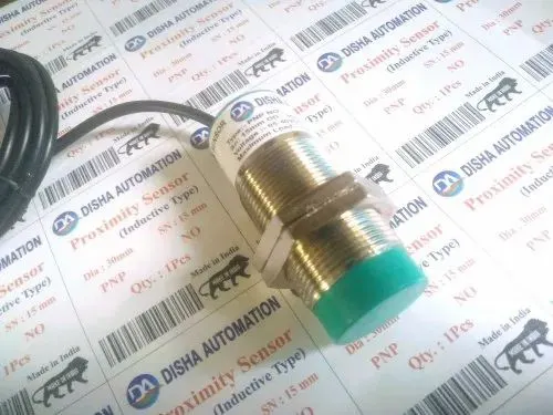
- A sensor unit is a unit designed to sense the car panel by using Electrical sensors. This signals from the sensors will be fed to the PLC and so the next process will be executed by this signal.
- In the fixture design we also seperate locators to position the sensors,thus when a the component is placed between the fixture unit the the sensor then sends the signals to the robot for the welding and other processes.
- It also ensures the placement of the BIW component correctly over the fixtures.
11. What are the types of the sensor?
Ans:
Types of sensors used in general:
1. Proximity sensors
2. LASER sensors
3. Photo electric sensors
4. Barrel Sensor
5. Sensor mounting bracket
12. What are the fundamental points that need to consider while designing or selection of sensor?
Ans:
Fundamental of Sensor Unit design:
- Every single loose panel which are being welded in a tool should be sensed.
- Each panel should be sensed by 1 to 2 sensors depend on the size of panel, Preferred to be in diagonal opposite ends of panel.
- Every sensor should be mounted in a 3 direction adjustable way in general.
- Some major sensor manufactures are IFM. Pepperl-fuchs, SICK, OMRON etc