Radar Mast & Final Assembly of Yacht
DESIGN AND ASSEMBLY OF PREDETOR YATCH
Introduction
The 3d model of Predator Yacht design in Solidworks. Predator is a super yacht built in 2008 at the Dutch shipyard Royal De Vries Aalsmeer.
OBJECTIVE
- The objective of this is project is to design and the Predator Yacht
- Assemble the components.
- Rendering for photo realistic visualization.
Overview of design:
(I ) modelling of parts
(II) Assembly
(III) Rendering
- Modelling of parts:
|
S.No |
Component |
No.of pcs |
|
1 |
Blueprint setup |
1 |
|
2 |
Propeller |
3 |
|
3 |
Radar |
1 |
|
4 |
Hull |
1 |
|
5 |
Garage door |
1 |
|
6 |
Front seat |
1 |
|
7 |
Middle seat |
1 |
|
8 |
Rear seat |
1 |
|
9 |
Superstructure |
1 |
|
10 |
Radar mast |
1 |
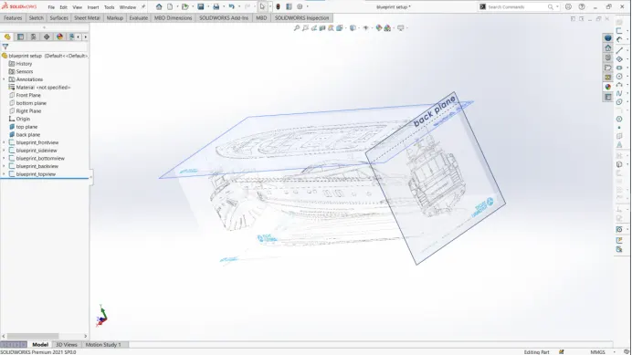
- Blueprint setup
- To start , setup the blueprints in respective to their planes
- Start a new part and setup the new planes following the dimensions
- Go to sketch entities and insert the respective sketch picture and adjust them in their respective planes as shown in the above diagram.
- Propeller
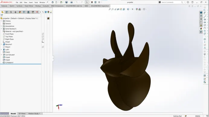
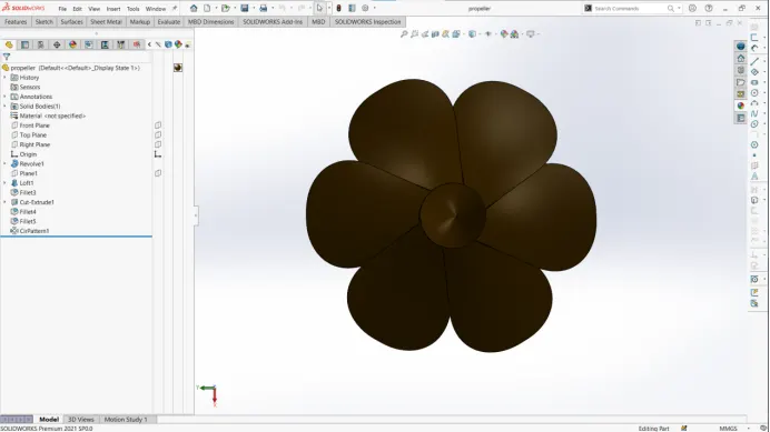
- To start with the propeller create the circular profile where the fins of propeller sit
- Then to create the profile of the fin , setup a plane at a certain distance then draw your sketch on circular shaft and plane
- Use the loft option in the features to create a profile which sweeps the material from one profile to another
- Next apply the fillet which gives it the circular geometry and use the circular pattern option which generates the geometry around the shaft as shown in above diagrams.
3.Radar
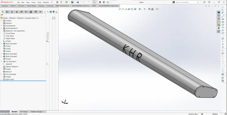
- To generate the radar , start with producing the profile using the boss extrude option
- Generate another profile on the side faces with act like the air flow vents and screws as shown in the diagram(you can produce all the necessary geometry in one face and mirror them with is better way)
- Create at bottom face where the radar is supposed to sit on with radar assembly
- Apply the fillets where ever as required following the dimensions.
4.Hull
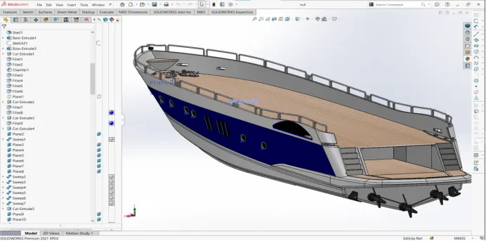
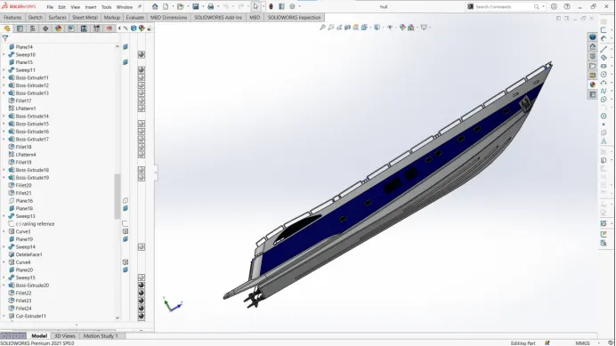
- To start the hull , start with the body.Draw two curves and make a projected curve then use the loft option to create the surface
- Then to to finish the rest of the base by selecting the edges and use loft option to generate the profile
- Trim the unnecessary surfaces and make the part closed by using the loft or filled surface
- Follow the blueprints as reference to draw the curves and profiles
- Use the surface knit option to combine the two different surfaces or any extra necessary if you had to redraw or repair geometry
- Use the shell and boss extrude options to make the hull hollow in the inside (follow the dimensions and sketch pattern to generate the profile)
- For the gaps in sides select the mid plane and use cut extrude option to remove the material
- For the windows (black coloured surface) ,first cut the material and and add plane on respective edge to draw the profile for sweep
- Then use have to use sweep option multiple times to generate the profile
- Do the same procedure for the bodies on the surface of the as well
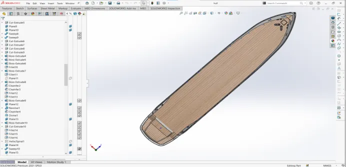
- Just follow the three steps for bodies to generate on specific position
- Insert the plane by selecting the edge or plane or draw a profile in specific position as a reference for plane to sit
- Draw the profile sketch on your plane
- Use extrude / revolve / sweep any necessary tool which can generate your profile and remove unnecessary material using the cut extrude / fillets / chamfers with ever tool is necessary
- Use the above procedure to create the anchor on the side face of the hull following the dimensions and adding necessary fillets and chamfers
- Select the surface/face and sketch the profile for steps and and generate the geometry
- Next select the top plane and sketch for bottom guide vanes and use extrude the profile choosing the offset from surface option.Add chamfers and fillets following the dimensions
- Next draw the sketch for rails on the sides , two sketches one for reference and another for guide for the projected curve and project the curve
- Next insert plane selecting the curve and point on curve as the reference and sketch the profile.Use the sweep option to generate the geometry as visible in the diagrams
- Do the same procedure for rails or handles on the hull
- Cut some material in the hull side face ( space for garage ) and save that cut part for the door which is next part.
- The last part would be the propeller guides and levelers on the back face
- To create the leveler simply select the face and generate the necessary geometry using boss extrude option and revolve boss for the handle and add necessary fillets and chamfers
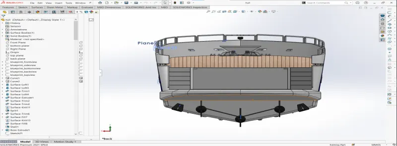
- Use the 3D sketch tool which is very handy, sketch the geometry and use boss extrude and revolve boss options to complete the body
- Next use linear pattern and generate another copy of it in certain position
- Last mirror your geometry and merge them , add appearances and decals on necessary positions.Select the surface of the hull and offset surface zero mm and save it for further reference.
5.Garage door
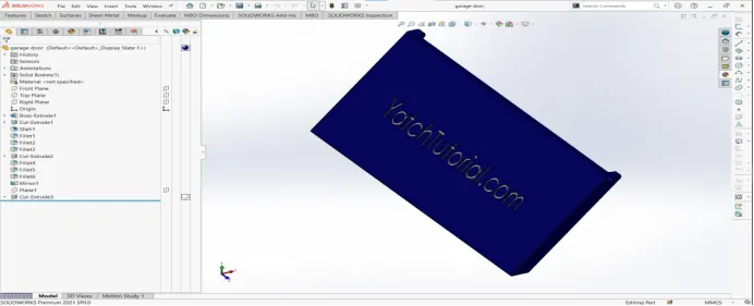
- Insert the part saved from the previous part and cut extrude on the edges and use the shell option to make the space in back side of the door
- Create holes on the edge faces which act like the holds for door
- Add fillets to the necessary edges and following the dimensions
- Next add text sketch to front plane and cut extrude upon the surface as seen in the diagram and add the appearances.
6.Front seat
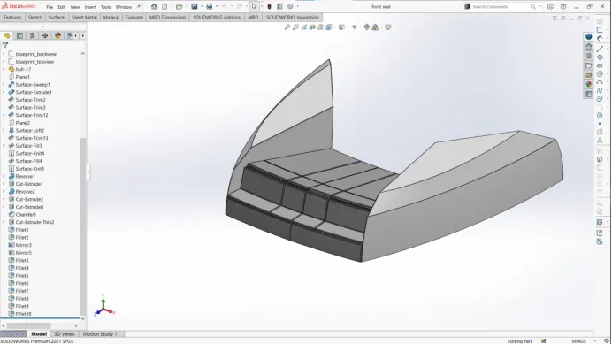
- To start with your geometry sketch the surface profile and use surface sweep to generate the surface body
- To fill in next use surface extrude option to to extend the surface
- Next trim the unnecessary surfaces and the knit the bodies
- To make it a closed profile use surface loft option and make your body a closed geometry
- Trim and knit the necessary and unnecessary bodies following the blueprints and dimensions
- Then select the mid plane face and sketch the seat profile and use revolve boss for generating your profile and also follow the angle (10 degrees) mentioned in your sketch blueprint
- Remove the unnecessary material using the cut extrude option and add fillets and chamfers where ever necessary
- Next select the mirrors option in the features tab and mirror your geometry with merge solids and make sure to knit surfaces so that you body is counted as one single body
- Add the appearances to body.
- Middle seat
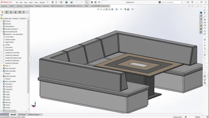
- For the middle its simple to genertae the geometry, sketch the base and insert a new plane on base surface and generate the seat body.
- Both the operations can be simply performed by using the boss extrude option following the dimension from the blueprints and positioning of the sketch
- Add the chamfers to the seat body as shown along with fillets which gives the look of seat inclination as you can see in the above diagram
- Using the same options and methodology you can generate the table body in the middle
- At last mirror your geometry so that you have a entire seat body
- Add the necessary fillets and appearances to your body.
8.Rear seat
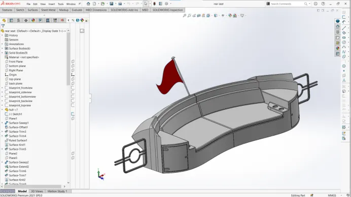
- To create the seat profile select the mid plane and use surface sweep to generate the geometry
- Offset the some part of surface as shown in diagram following the dimensions and extend the surface to make it closed
- Trim all the unnecessary surfaces and knit them with gap control maintained
- Next do another sweep profile to complete the profile and trim the extra surface and knit the body to one
- Extrude the edge to a face using the surface extrude sketched in the hull surface face and trim the extra edges
- Next use either the loft option or filled surface option to fill the space between offset surface and seat surface
- And overall trim the extra edges and surfaces and knit the body to one
- Sketch the profile of flat seat from the surface of the hull using the boss extrude option , use convert entities option in sketch to make geometry model faster
- Offset the surface of the flat seat of the seat and extrude it.
- Do the same for the vertical seat surface and add fillets and chamfers to the bodies
- Next for cut extrude part on the front part corner sketch on the front plane and cut extrude
- For side gate insert a plane following the dimensions and sketch sweep path , next insert another plane on the sketch as reference and sketch the profile for sweep
- Use the sweep option to generate the geometry and mirror it with respect to plane of sweep profile which will give a closed loop as shown in the diagram
- Next mirror the entire geometry with respect to the middle plane and merge solids to complete the geometry as one and add appearances and necessary fillets and chamfers.
9.Superstructure
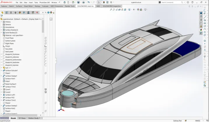
- Most of the superstructure involves working with tools of surface features
- Insert the offset surface from the hull and start on it
- To generate geometry of superstructure it involves
- Projected curves , cause most of the structure is curved we expect it mostly drawn with respect to two different sketches which gives us precision for surface generation
- Surface extrude , which we use to produce the the surface of the sketch , the sketch will be open mostly when we are working with surfaces though
- Surface sweep similar to the concept of sweep from solids , profile of the surface and path of sweep
- Surface extend , we extend the surface from the edge to extra with multiple options like divergence or angle of extend , even though most of sketching part in surfaces are open they have to be fully defined
- Loft , loft is similar to solid loft but with different surface profiles with guides and splines , which is very handy tool in surfaces
- Ruled surface , to extend surface with curvature
- Filled surface , we use to close the surface with is open like inert a lid upon a open box.To fill the surface convert the sketch should be closed
- Most important tool is trim, where we rem0ve/cut/keep the useful or unnecessary surfaces , the trim works properly only the surfaces are interacting or intersecting
- It certainly is most important to knit the surfaces with gap control so that your sketch is fully defined without any open spaces or gaps between the surfaces
- Following the blueprint setup and dimensions the superstructure is produced easily but its important to check for the surfaces are fully defined and after completing the whole surface body it is counted as one surface body
- Also make use of the 3d sketch tool where we can convert entities of edges without selecting or separately inserting new one
- For seat part on the front of superstructure involves solid modelling and extrude them offset from surface option is which we widely use for solid bodies which we model on surface bodies
- We do have to add the fillets and chamfers where ever they are necessary following the dimensions
- For surfaces edges fillets can be showing error , then we cab either ignore them or we can repair them if the chamfer/fillet is really necessary
- At last add the appearances and decals to the body and select top edge surface and offset surface it to zero mm as a reference for radar mast.
10.Radar mast
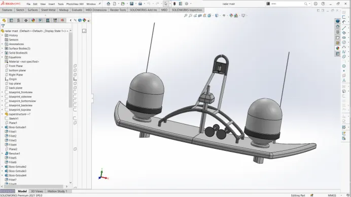
- Insert the offset the surface from the superstructure and start on it
- Create base by sketching on the new plane which we inert selecting the offset surface
- Use the top blueprint as reference for for the sketch and fully define it by following the dimensions , use boss extrude to generate the geometry
- For the circular boss , insert a new plane and sketch on it . use the revolve boss option to generate the geometry
- For the curved handle and the antenna , use the projected curves and insert the plane to generate the sweep profile
- To create the horns , insert the new plane from mid plane and sketch on it , use the revolved boss option to generate the geometry and use linear pattern to produce copy of it
- At last add the appearances and fillets/chamfers to the body.
- Assembly:
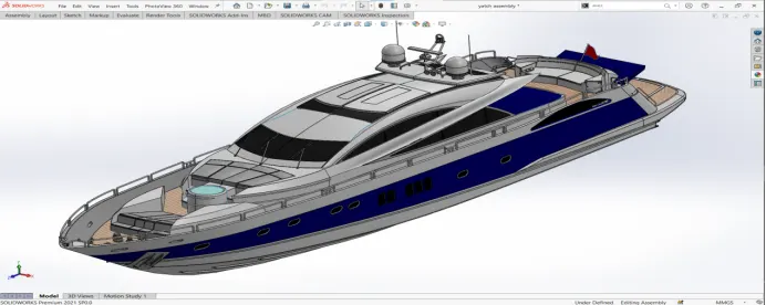
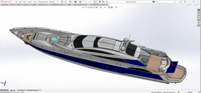
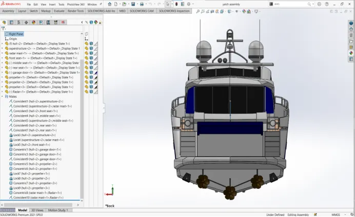
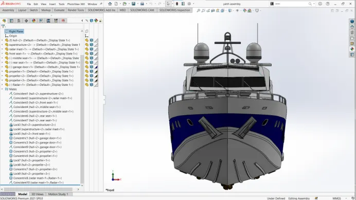
- Its very easy to work with assembly , cause most of the geometry sits on the hull part
- Insert the hull part first then insert all the remaining part which automatically sit references, cause their position is defined on reference surface of the hull
- Insert the radar mast and it should sit on the top surface of the superstructure , then insert the radar to its insert on mast
- Finally insert the garage door to its position on the hull.
YATCH RENDERS
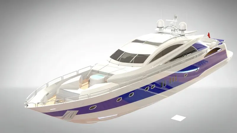
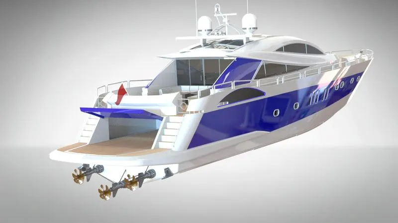
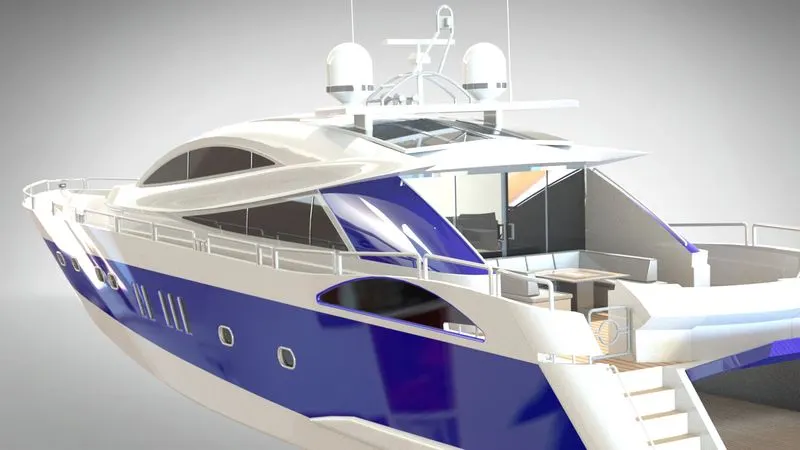
- Rendering is done in Solidworks visualize , the decals and the lighting positioning , camera positioning is set in renders option in solidworks by activating the photoview360.
Conclusion
- The modelling of the each part of predetor yacht is done separately with unique appearance
- All the modelled parts are assembled together and mates are assigned
- The final rendering is done in solidworks visualize