Week 8:- 3D Finishing - Challenges 1
1.What do you understand by the 3D finish process?
3D finish is a process where the design is being completely finish and to be ready for final simulation & 2d detailing.
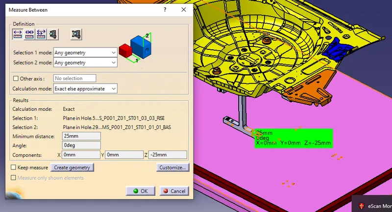
Angle between base unit and riser base
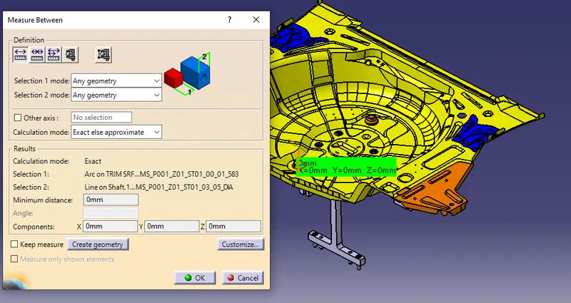
Concentricity between the hole and pin
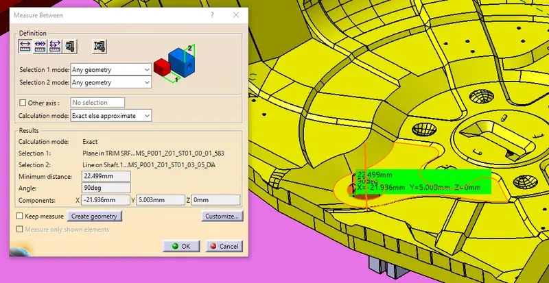
Perpendicularity between the surface and pin
2. What are the points need to be taken care of while finishing the design?
Following points need to be taken care while finishing your design.
- Hole concentricity & hole sizes
- Machining area
- Nominality
- Holes colouring standard
- Pneumatic layouting
- Gaps checking
- Fasteners implementation
- Avoiding clash between different parts Mylars Splitting as per panel profile
- Proper renaming of parts/assemblies as per the standard.
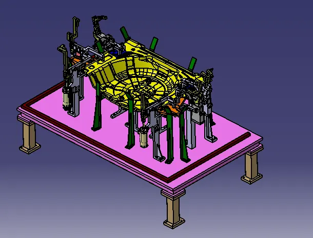
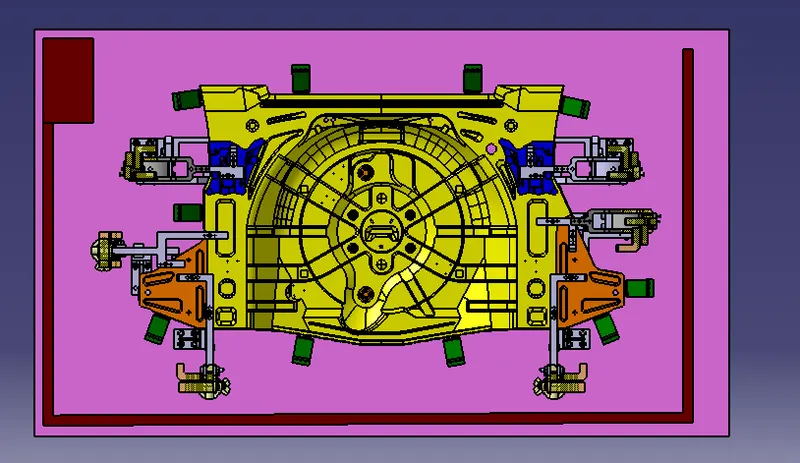
3. What are rough Locators & what is their use?
- Rough locators are basically used where manual loading of panels are to implemented on the fixture.
- These are used to guide the panels in correct position & orientation.
- These also help for proper Poka -Yoke. Materials used for rough locators are MS or similar metal.
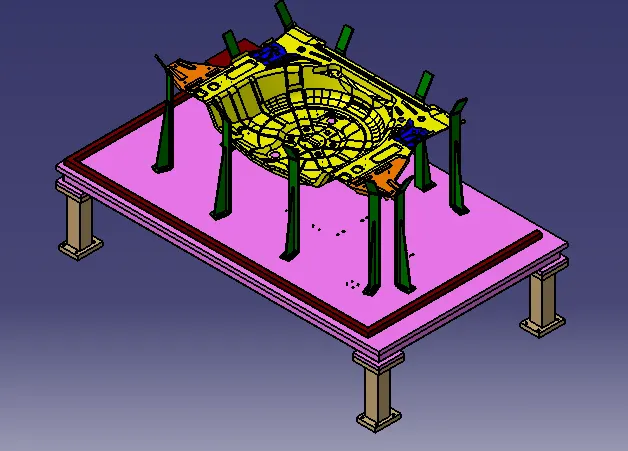
4. What are the points you need to consider while designing a rough locator?
Following points need to be considered while designing the rough locators,
- Height of rough locators should not be more than the permissible ergo height of the fixture.
- The entry point/ top point of the rough locator must be 20mm-25mm above the panel surface.
- Rough locators should have adjustment in the direction of guiding plane.
- 2 mm gap to be maintained between rough locator and panel at the time of design & we can provide adjustment of 5-10 mm in the positive or negative direction of guide plane.
- Rough locators can be rod type or flat type, depending upon the standards and other conditions.
5)What is the gun study process?
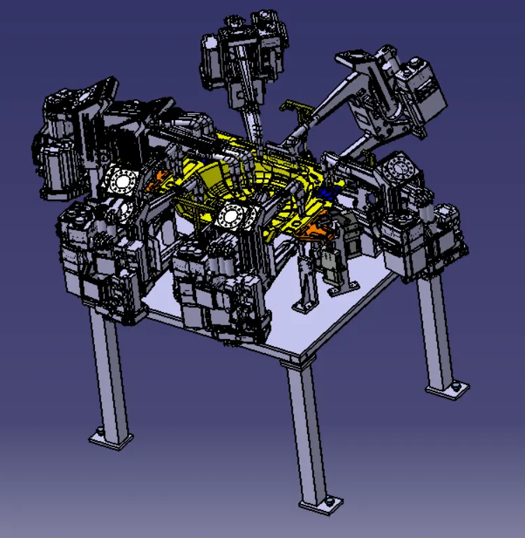
- Gun Study is a process where positioning of spot gun or weld torch is to be checked, to avoid clash between gun & other parts of the fixture & check the gun feasibility.
- In this process designer usually takes the gun tip to respective spot or weld position at various orientation & checks if there are any clashes between any part of the gun & fixture.
6)What are the points need to consider during the gun study?
Following points need to be considered while doing the gun study,
- Min gaps to be maintained between gun & other parts of fixture is 5mm-10mm.
- We should always keep in mind that, there must be no clash while the gun is moving in & out of the fixture.
- Whether the prescribed gun is suitable to weld the required number of welds or there need to be some changes required.
- Also check the weld height should be as per the ergo for manual welding stations.
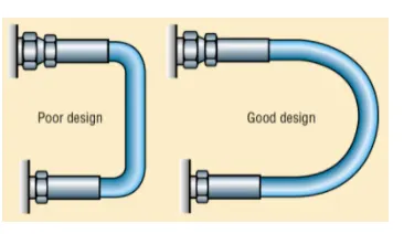
7)What is pneumatic routing?
Pneumatic system- System operated with Air.
- Open loop system Generally used for low pressure
- Generally deliveres less force compared to hydraulic system
- Cheaper compared to hydraulic for basic cost,but compressor running cost is more
- Pneumatic system is mostly preferred over hydraulic system in BIW welding fixture.
- All toggle clamp , pin cylinder, slides are operated via pneumatic.
- Generally cylinder are designed to operate max pressure 12-13 bar.
- As it expensive and difficult to maintain 10-12 bar in shop floor it is preferred to do design pneumatic systems at 6 bar pressure
8) What is the solenoid valve?
A solenoid valve is an electrically controlled valve. The valve features a solenoid, which is an electric coil with a movable ferromagnetic core (plunger) in its center. In the rest position, the plunger closes off a small orifice. An electric current through the coil creates a magnetic field. The magnetic field exerts an upwards force on the plunger opening the orifice. This is the basic principle that is used to open and close solenoid valves.
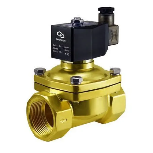
A solenoid valve consists of two main components: a solenoid and a valve body.
A solenoid has an electromagnetically inductive coil around an iron core at the center called the plunger. At rest, it can be normally open (NO) or normally closed (NC). In the de-energized state, a normally open valve is open and a normally closed valve is closed. When current flows through the solenoid, the coil is energized and creates a magnetic field. This creates a magnetic attraction with the plunger, moving it and overcoming the spring force. If the valve is normally closed, the plunger is lifted so that the seal opens the orifice and allows the flow of the media through the valve. If the valve is normally open, the plunger moves downward so that the seal blocks the orifice and stops the flow of the media through the valve.
Solenoid valves are used in a wide range of applications, with high or low pressures and small or large flow rates. These solenoid valves use different operating principles that are optimal for the application. The three most important ones are explained in this article: direct-acting, indirect-acting, and semi-direct acting operation.
9) What is the valve bank?
The valve is actuated by selectively energizing the corresponding solenoid to allow servo air to the servo port of the valve. To return the valve to its fail-safe position, the solenoid is de-energized to vent the servo port of the valve to the ambient.
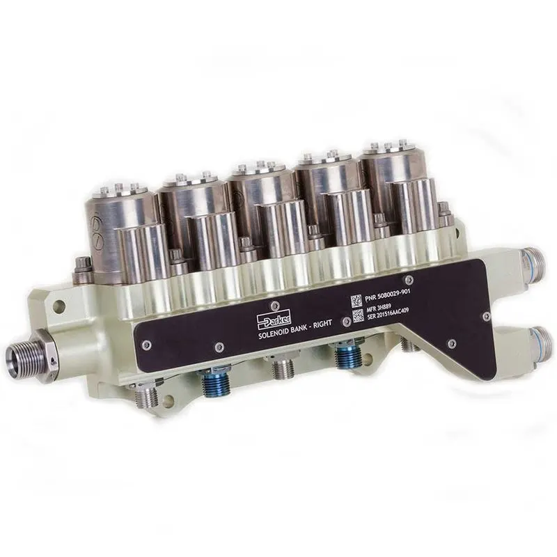
The solenoid bank is designed with an inlet port, a single servo line to each of the pneumatic valves, and independent vent passages for each solenoid.
The solenoids are two-stage pilot valves and are normally open with the solenoid de-energized, allowing high-pressure supply air to the servo ports of the downstream pneumatic valves. Energizing the solenoid blocks high-pressure air supply and simultaneously vents the pneumatic valve servo chamber to the atmosphere, closing the respective pneumatic valve.
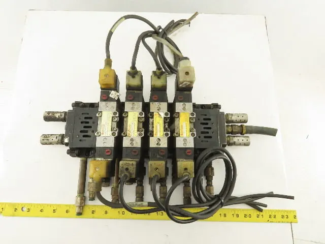
The Parker two-stage solenoid is designed to provide fast response times. The electrical configuration is a dual-coil redundant design providing an isolated circuit topology housed in a single package. Each coil is independent and identical in function.
- Designed for high vibration levels
- Uses aluminum alloy manifolds for lightweight
- Designed for high-temperature environments
- Design architecture allows easy selection of two to six solenoid valves
10) What is sensor & brief about its application in automation?
A device that detects, measures, and converts a physical quantity into a signal that can be read by an observer or an instrument. A sensor allows us to notice things and understand them easily.
The sense organs that we have are considered to be Natural sensors and based on these sensors, we have many man-made or artificial sensors that allow us to make our life easy day by day. Artificial sensors are hardware components that can allow a device to know its location, surroundings, and many more things. These can be either wired or wireless.
Positioning and Displacement
That is, it measures the distance traveled by a device starting from its reference position. Based on the motion of a device, the position sensors used in them are categorized as Linear Position sensors or Angular Position Sensors.
Linear Position Sensor:
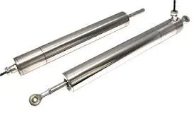
It measures the linear position of a device. It is a type of transformer that is used to sense and measure linear displacement.
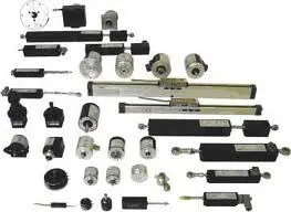
Angular Position Sensor: This sensor often referred to as a rotary sensor calculates the orientation of an object to a specific reference position as has been expressed by the amount of rotation necessary to change from one rotation to the other about a specific axis. It measures the relation established by any position to any other position. These are used, where long-term reliability is required.
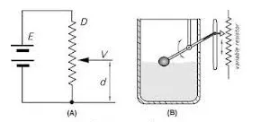
Potentiometric position sensors:In these types of sensors, the position marker is attached to the moving part of the application, whose position needs to be measured. The sensing element is a resistive or a conductive track, where a wiper (for example) is attached to the part of the device, whose displacement has to be measured.
11) What are the types of the sensor?
Vision and Imaging Sensors
Vision and Imaging Sensors/Detectors are electronic devices that detect the presence of objects or colors within their fields of view and convert this information into a visual image for display.
Temperature Sensors
Temperature Sensors/Detectors/Transducers are electronic devices that detect thermal parameters and provide signals to the inputs of control and display devices.
Radiation Sensors
Radiation Sensors/Detectors are electronic devices that sense the presence of alpha, beta, or gamma particles and provide signals to counters and display devices.
Proximity Sensors
Proximity Sensors are electronic devices used to detect the presence of nearby objects through non-contacting means.
Pressure Sensors
Pressure Sensors/Detectors/Transducers are electro-mechanical devices that detect forces per unit area in gases or liquids and provide signals to the inputs of control and display devices.
Position Sensors
Position Sensors/Detectors/Transducers are electronic devices used to sense the positions of valves, doors, throttles, etc., and supply signals to the inputs of control or display devices.
Motion Sensors
Motion Sensors/Detectors/Transducers are electronic devices that can sense the movement or stoppage of parts.
Metal Sensors
Metal Detectors are electronic or electro-mechanical devices used to sense the presence of metal in a variety of situations ranging from packages to people.
Level Sensors
Level Sensors/Detectors are electronic or electro-mechanical devices used for determining the height of gases, liquids, or solids in tanks or bins and providing signals to the inputs of control or display devices.
Humidity Sensors
Humidity Sensors/Detectors/Transducers are electronic devices that measure the amount of water in the air and convert these measurements into signals that can be used as inputs to control or display devices.
Flow Sensors
Flow Sensors/Detectors are electronic or electro-mechanical devices used to sense the movement of gases, liquids, or solids and provide signals to the inputs of control or display devices.
12) What are the fundamental points that need to consider while designing or selecting the sensor?
Range: Difference between Maximum and Minimum value which can be sensed by the sensor.
Resolution: The smallest change which can be sensed by the sensor. (Should be High)
Sensitivity: Ratio of change in output to a unit change in the input.
Error: Difference between the Measured Value and True Value.
Accuracy: It is inversely proportional to Error, i.e. How close the sensor reading is to the True Value. (Should be high)
Precision: Ability to give/reproduce accurate value repeatedly. (Should be high)
Response Time: Time lag between the Input and Output. (Should be Minimum)
Signal-to-noise Ratio: Ratio between the magnitude of the signal and the noise at the output.
Calibration: As sensors need frequent calibration, they should be easy to calibrate.
Cost: It shouldn’t be expensive.
Nature of Output: Do we need Analog output or Digital output, it should be clear.
Environment: It is one of the most important parameters because not all sensors can work in extreme conditions. Sensors can get affected due to non-ideal conditions(like temperature, humidity, etc.) which may affect the output of the sensor.
Interfacing: It should be compatible to use with a wide range of instruments.Some sensors need an external power source to produce an output, so it is important to provide the power source so that additional errors arent introduced.
Size and Weight: Sensors should be compact and lightweight.