Week 8:- 3D Finishing - Challenges 1
Question 1. What do you understand by the 3D finish process?
ANSWER:
- 3D finish is the process where design is being completely finish & to be ready for final simulation & 2D detailing . While finishing the design the nominality of holes is checked which ensures the easy assembly of all the units.
- The hole concentricity & holes sizes are checked which ensures the easy assembly of different parts.
- The gaps between the different units are used to ensure the proper in working units.
- Fasteners are implemented as per the hole size & the standard color codes as per the customer requirements are applied to differentiate the type of hole whether it's a simple hole, threaded hole or counterbore hole.
- Renaming the assembly & the part is done to give every part a different identity. So everyone can identify in which assembly the particular part is going to be fit.
- After doing all these things the model is sent for to simulation department to Simulate the design with robots whether the gun is clashing or not & 2D detailing.
Question no 2. What are the points need to be taken care of while finishing the design?
ANSWER
Following points are taken into consideration while finishing the design
- PANEL DATA
- WELDING & RIVERT POINTS
- PPSL PURCHASE PART SOURCE LIST
- PLP-PRINCEPLE LOCATING POINT
- START FROM NC- NUMERICAL CONTROL
- BASE MOUNTING POSITION VALUE
- BUY OFF SHEET
- COLOUR CODE DATA
PANEL DATA:
- Panel knowledge
- Check mis-assemble in panel Number of panel.
WELDING & RIVERT DATA:
- Get welding & rivet data from costumer
- Welding & nvet operation process
PROCESS FOR DESIGN:
- Sketch should be fully constrained
- Gas cut profile should be in thickness face with edge fillet
- 3mm radius for <50mm thickness
- 5mm radius for> 50mm thickness
- If use 5mm radius for 20mm plate it will remove material is large than 3mm
- Rough machining
- Fine machining
- Maintain 3mm machining step
- Clearance 3mm between shim and machining step
- in some case 2mm and 2.5mm machining step can use
- edge fillet 5mm, it depends upon tool diameter
- Avoid unnecessary fine machining
- Holes
NC-NUMERICAL CONTROL
- Start fromnic
- Nc charping surface should cover 16mm diameter of plp point
- Nc should be in absolute and have round off value in xyz drection.
- Nc clamping should be in plain surface (no bend, curved surface), if two or three panels are there, having same plp the clamping surfacemust be common for both panels.
- Maintain minimum clearance 15mm between nc(make parts) to panel and weld points.
- Maintain clearance 10mm in special case 5mm.
- Mention non-magnetic stainless steel (nmss) note if welding point is very close to nc.
- Length of nc small in size to avoid vibration.
MAKE PART:
- Overall length should not be in 0.5 value both honzontal & vertical like 95.5
- Add rib if required to avoid over hanging
- design weldment in part body or product depend upon no. Of parts
- welding clearance.
- weldment clearance minimum 5mm.
GENERAL CHECK LIST:
- Unit should be in absolute in tool vise
- All nc should be in absolute
- Nc face should be round off except angle ne fround off in one side)
- Gas cut profile there should be there.
- Thichness fase machining step depend on stock size
- Ncdowel should be in slip fit e8 and mounting part should have press fit
- Riser base mounting in slip fit e8
- Hule should be inline
- Check clash anlyss
- Colour code.
Question 3. What are the rough locators & what is their use?
ANSWER:
- A rough locator is a part designed to guide the operator, to locate the car panel on to the pins accordingly. A rough locator can be of standard part or make part.
- Rough locators are used to help locate work pieces in the automation process Locating refers to the desired location where we want the work piece to be sitting when it is getting on either worked on either by a person, team, or a robot.
- Body part rough locators are provided to assist manual part loading to the tool.
- The following are general guidelines for rough locators:
- It is not required to finish cold/hot rolled steel for rough locator mounting Use NAAMS standard rough locators when possible.
- if possible, do not place rough locators in positions that force the operator to lift and load, or unload the part over the rough locators
- Rough locators must be designed with slots for ease of adjustment Rough locators should have minimal part contact so that the operator can load the part to work location with ease. Excessive part contact may cause difficult part loading and unloading .
- Rough locators must never touch the part when it is nested or controlled by the primary tool locators
- If the rough locator requires a unique design, use the design parameters for the standard NAAMS rough locator as a guide.
- A rough locators is a part designed to guide the operator, to locate the car panel on to the pins accordingly. A rough locator can be a standard part or make part.
- It is used to identify the correct orientation of the panel.
- It can be called as fool proofing method also. Because due to the rough locater the part cannot be loaded in incorrect position. locations are set according to the angle of the respective panel hence part, can only be loaded in defined orientation
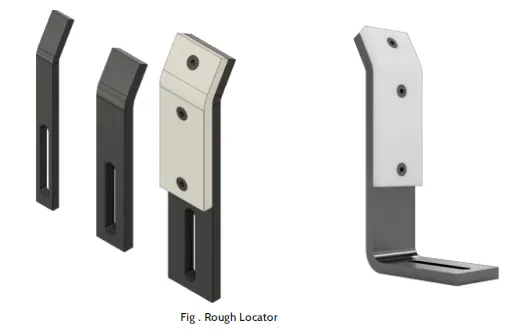
Question 4. What are the points need to consider while designing a rough locators?
ANSWER:
- Following are the points need to be considered while designing the rough locator.
- Rough locators should be placed at the edges of the car panel, which it has to guide.
- Rough locators has to be placed in the same angle of the car part edge with a minimum distance of 2-5 mm from the edge of the car panel.
- Rough locators should guide the panel in pin arresting direction.
- Rough locators should start guiding the panel before 10 to15mm to the start of the pin engagement.
- Rough locators should be designed with entry angle for the car panel. Generally it ranges between 30-45 degree.
- Rough locators should be designed with two slots to mount the easy adjustments.
- The slots should be in the direction of car part guiding,Rough locators must be designed with slots for ease of adjustment.
- Rough locators should have minimal part contact so that the operator can load the part to work location with ease. Excessive part contact
- may cause difficult part loading and unloading
- Rough locators must never touch the part when it is nested or controlled by the primary tool locators.
Question 5. What is the gun study process?
ANSWER:
- Welding is mostly used in automobile industries and their requirements for fixtures that ease the welding process is a continuous developments task in any industry.
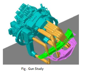
- In weld study process, the major procedure is insert the gun in the tool assembly and place the gun on the weld spots by creating a point
- on the tip. Adjust the weld the weld gun for not getting any clashes from the 3D concept. . Once all the weld spots are cleared without any clashes and it will be moved on to next procedure of simulation.
- In simulation, first we have to check with the reach with respect to the weld spots. Because robots are also having some limitions if it exceeds the robot will not work proper with 100 percent. So first we have move with reach check and then try to adjust the weld gun with respect to 3D concept design. If any clashes gets in simulation, we will get cleared with CATIA software.
- Car Body In White (BIW) is a complicated steel structure including 300-500 sheets with complex shape and are assembled by means of welding in a high trhythm through 55-75 robotic workstations
- The fore most step taken before starting the welding fixture design, we must declare weld spots location for each and every panel. The location and orientation of other critical units of the foxture including clamps, locators, etc are decided based on the weld spot distribution
- Now coming to the point, in weld study, first we have to choose which gur has to be used for welding process Gun have two different types, they
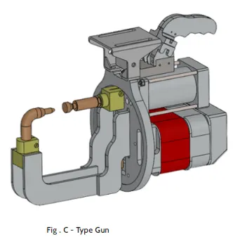
- C-Type gun.
- X-Type gun
C-Type gun:
- In C-type gun onie arm side is fixed and another amis mevable in lindar direction of perpendicular to other arm Honzontal direction with respect to other arm.
X-Type gun:
- In X-type gun one arm side is fixed and another arm is movable in angle position like (it moves like an arc).
- It includes the study of the weld matrix & the weld point positions. There are two types in weld point one is Geo geometry of the assembly & second is Re-spot weld points which adds strength to the welded parts weld which ensures the
- The fixture is designed for the car panel to hold it on the position, so we ensures all the weld spots and weld gun do not across or any clashes with fixture tool.
- If any clashes defined while designing fixture, then we will only move on to redesign the tool. We have no permission to change a weld spot or clamping position without considering clients.
Question 6. What are the points need to consider during the gun study?
ANSWER:
- Weld gun study is very time consuming process, the entire welding cycle time study depends on the no. of spots & the weld gun study.
- Following are the points need to consider during gun study.
- The axis of weld spot along welding direction must be normal to the weld surface. . The no. of weld spots for the panel the time required to spot the each weld & the total time required to complete all the weld spots.
- We have only access to rotate the weld gun on Z axis. Because if we rotate the weld gun on X and Y axis the weld spots quality will reduce and the precision will get lost.
- During gun study we have to consider clients cycle time and we have to maintain the cycle time compared to clients requirements. There are two types of weld spots they are geo spot and respot and these two spots are having different timings
- Geospot-3sec.
- Respot-2.5sec.
- If we have one or more device models and we want to program, the behavior of each model in the work cell can be simulated over time. Instruction for each device are coded by giving sequence.
- If we have no issue with weld gun and we have to move on to next procedure to run the paths (path ways) to analyse there is any clash while weld gun reach a weld spots and then if we done with that and finally move to Sequence of operation.
- After sequencing all the device and paths and finally simulation is run with collision check on and make sure all the weld spots and paths are clear from collision which using safe robots.
Question 7. What is Pneumatic routing?
ANSWER:
- Pneumatic systems should be efficient and leak free. Sometimes, they are not, because of improper tube line routing-the result of either lack of knowledge or comers cut on planning time or both.
- Planning tube line routing is a time investment, but it can have a big ROI especially for complex systems. During system design, routing should be developed as the next step after sizing the tube lines and selecting the appropriate fittings.
- Here are some guidelines for planning appropriate tube line routing
- Lease fitting joints as accessible as possible. Inaccessible joints are difficult and time-consuming to assemble, tighten and service.
- Use software tools to make labor intensive calculations such as pressure drop.
- Employ U-bends to allow for line contraction and expansion.
- Include offset bends to allow for motion under load, regardless of how rigid the system seems.
- Favor bends rather than straight tube lines, because a straight line tube assembly with no bends, like the example of the test stand mentioned above, can cause joint stain, which may lead to leaking.
- Make sure routing design allows room for assembly of any connections required.
- Minimize pressure drop by getting around obstructions with as few 90 degree bends as possible. One 90 degree bend has more pressure loss then two 45 degree bends.
- Route lines around rather than over areas that require regular access or maintenance
- Design routing with clamping in mind. Appropnate design leads logically to proper clamping. Often its possible to clamp several lines together
- Keep trouble shooting and maintenance in mind focus on logical design and avoid crossed lines.
- Design the tube line routing to reduce likelihood of users standinger climbing an plumbing.
Question 8. What is solenoid valve?
ANSWER:
- Solenoid valves are electrically activated valves, typically used to control the flow or direction of air or liquid in fluid power systems Used in both pneumatic and hydraulic fluid power functions, the spool or poppet design of most solenoid valves makes them perfect for various functions and applications
- Atos On-Off solenoid valvesThe spool or poppet of the valve connects to a ferrous metal plunger, which is typically spring centered or spring offset, but may be detented instead. The plunger slides within a core tube of non-ferrous metal, itself surrounded by a coil of electrical windings. The coil exists with any range of voltage from 12-48 Vdc to 110-220 Vac. When power is sent through the coll, a magnetic field is created, which pushes or pulls the plunger, shifting the valve
- The most basic solenoid valves are two-way, two-position poppet valves, which simply open and close, modifying their flow path when their coll is energized. They are available as "normally-open" and "'normally-closed" versions, which means normally-flowing and normally blocked, respectively. Normally-open in fluid power contradicts normally-open in electronics, which stands for the switch or contact open and not flowing electrons
- Three-way two position poppel valves are also common diverting flow from one channel to another. Two 3/2 valves in parallel can be used to control a cylinder bidirectionally Although construction vises depending on the use, this type of valve can be used for either pneumatics or hydraulics, but is more common to prieumatic systems.
- Spool solenoid valves consist of a machined spool which slides within a machined valve body. One or both ends of the spool are acted upon by a plunger, and when activated by either coll, pushes the spool one way or the other allowing three positional envelopes The 4/3 hydraulic solenoid valve is one of the most popular, allowing for bidirectional control of a cylinder or motor from a single valve body. The Tways of a solenoid valve refer to how many ports it contains, and the "positions of a solenoid valve refer to how many discrete states in which it openites A three-position valve employsn spring centered neutral state along with two actuated positions
- For bidirectional motor orcylinder control pricuratic valves are machined with five ports, and are referred to as 5/3 valves is common practice. The ways of apreumatic valve also include its ef vust ports, to which there are usually two Ochoonally these same Valves are described as 4-way 3-position valves, even though clase spurten uveals the two exhaust ports bisecting the pressure plant.
- Solenoid valves for either hydraulic or pneumatic applications are available as manifold-mounted modular units, such as the pneumatic or hydraulic ISO valves. These valves contain standard mounting and porting patterns, permitting valves from any manufacturer to be installed upon the same manifold. Most often, these valves are also quite economical, and readily available "off-the-shelf
- The electrical coils of a solenoid valve are optioned with either DIN connectors, lead wires, Deutsch connectors, central connection or any other popular form of electrical connection used in fluid power and automation. Most solenoid valve coils are field replaceable, making repair and maintenance easy for technicians, Coils also have a wide range of application and purpose. Some are intended for the industrial environment, where atmospheric conditions are consistent, Mobile environments are much more demanding and command coils to handle both extreme temperature ranges and exposure to road film and salt, for example.
Question 9. What is the Valve bank?
ANSWER:
Valve bank is the arrangement of no of solenoid valves
Valve bank will have common intet port a single servailine to each of the preumatic valves and independent vent passages for each solenoid
On the solenoid bank, each of the solenoid valves separately controls the feed of high pressure servo air to a simple pneumark valve. • The valve is actuated by selectively energizing the corresponding solenoid to allow servo air to the serve part of the valve: To return the valve to its fall safe position, the solenoid is oe-energized to vent the servo port of the valve to ambient
The solenoids are two stage pilot valves and are normally opery with the solenoid de-energized allowing high pressure supply ait to the servo ports of the downstream pneumatic valves Energing the solenoid blocks high pressure air supply and simultaneously verts th pneumatic valve servo chamber to atmosphere. Using the respective pneumatic valve
The two stage solenoid are designed to provide fast response tres. The electrical configurations a Just-oil reductant design providing an isolated circuit topology housed in a single packaged.
Common features of valve bank.
- These are designed for high vibration levels.
- It uses aluminium alloy manifolds for light weight.
- These are designed for high temperature environments.
- Design architecture allows easy selection of two to six solenoid valves.
Question no 10. What is sensor & brief about its application in automation?
ANSWER:
A device that detects the changes in electrical or physical or other quantities and thereby produces an output as an acknowledgement of change in the quantity is called as a Sensor, Generally, this sensor output will be in the form of electrical or optical signal.
Real Time Application of Sensors:
- The example we are talking about here is the Autopilot System in aircrafts, Almost all civilian and military aircrafts have the feature of Automatic
- Fight Control system or sometimes called as Autopilot.
- An Automatic Flight Control System consists of several sensors for various tasks like speed control height position. doors. obstacle. fuel. maneuvering and many more A Computer takes data from all these sensors and processes them by comparing them with pre-designed values.
- The computer then provides control signal to different parts like engines, flaps, rudders etc. that help in a smooth flight. The combination of Sensors, Computers and Mechanics makes it possible to run the plane in Autopilot Mode.
- All the parameters i.e. the Sensors (which give inputs to the Computers), the Computers (the brains of the system) and the mechanics (the outputs of the system like engines and motors) are equally important in building a successful automated system.But in this tutorial, we will be concentrating on the Sensors part of a system and look at different concepts associated with Sensors (like types, characteristics, classification etc.).
Question no 11. What are the types of sensor?
ANSWER:
The following is a list of different types of sensors that are commonly used in various applications. All these sensors are used for measuring one of the physical properties like Temperature, Resistance, Capacitance, Conduction, Heat Transfer etc.
- Temperature Sensor
- Proximity Sensor
- Accelerometer
- IR Sensor (Infrared Sensor)
- Pressure Sensor
- Light Sensor
- Ultrasonic Sensor
- Smoke. Gas and Alcohol Sensor
- Touch Sensor
- Color Sensor
- Humidity Sensor
- Tilt Sensor
- Flow and Level Sensor
We will see about few of the above mentioned sensors in brief. More information about the sensors will be added subsequently A list of projects using the above sensors is given at the end of the page
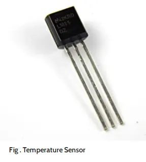
Temperature Sensor
One of the most common and most popular sensor is the Temperature Sensor. A Temperature Sensor, as the name suggests, senses the temperature Le. it measures the changes in the temperature.
Proximity Sensors
A Proximity Sensor is a non-contact type sensor that detects the presence of an object. Proximity Sensors can be implemented using different techniques like Optical (like Infrared or Laser), Ultrasonic, Hall Effect, Capacitive, etc.
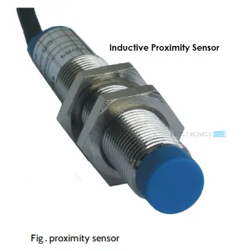
Some of the applications of Proximity Sensors are Mobile Phones, Cars (Parking Sensors), industries (object alignment), Ground Proximity in Aircrafts, etc.
Proximity Sensor in Reverse Parking is implemented in this Project: REVERSE PARKING SENSOR CIRCUIT.
Infrared Sensor (IR Sensor)
IR Sensors or Infrared Sensor are light based sensor that are used in various applications like Proximity and Object Detection. IR Sensors are used as proximity sensors in alrdost all mobile phones.
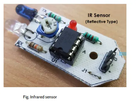
There are two types of Infrared or IR Sensors: Transmissive Type and Reflective Type In Transmissive Type IR Sensor, the IR Transmitter (usually an IR LED) and the IR Detector (usually a Photo Diode) are positioned facing each other so that when an object passes between them, the sensor detects the object.
The other type of IR Sensor is a Reflective Type IR Sensor. In this, the transmitter and the detector are positioned adjacent to each other facing the object. When an object comes in front of the sensor, the sensor detects the object.
Different applications where IR Sensor is implemented are Mobile Phones, Robots, Industrial assembly, automobiles etc.
A small project, where IR Sensors are used to turn on street lights: STREET LIGHTS USING IR SENSORS.
Ultrasonic Sensor
An Ultrasonic Sensor is a non-contact type device that can be used to measure distance as well as velocity of an object. An Ultrasonic Sensor works based on the properties of the sound waves with frequency greater than that of the human audible range.
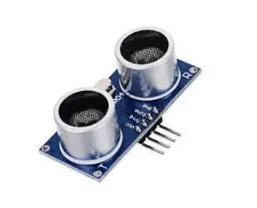
Using the time of flight of the sound wave, an Ultrasonic Sensor can measure the distance of the object (similar to SONAR). The Doppler Shift property of the sound wave is used to measure the velocity of an object.
Arduino based Range Finder is a simple project using Ultrasonic Sensor: portable ultrasonic range meter.
The following is a small list of projects based on few of the above mentioned Sensors.
- Light sensor-light detector using Idr
- Smoke sensor-smoke detector alarm circuit
- Alcohol sensor-how to make alcohol breathalyzer circuit?
- Touch sensor-touch dimmer switch circuit using arduin
- Color sensor-arduino based color detector
- Humidity sensor-dht11 humidity sensor on arduino
- Tilt sensor-how to make a tilt sensor with arduino?
Question no 12. What are the fundamental points that need to consider while designing or selection of sensor?
Answer:
The most common types of sensors used in manufacturing, factory automation, and machine control are proximity sensors, position sensors. inductive sensors, flow sensors, optical sensors, and vision sensors. A signal converter is a critical related technology. Here is my list of the top operating condition requirements:
1 Accuracy & Precision.
2. Environment.
3. Signal Conditioning
4. Response speed.
5. Sensing range
6. Repetition accuracy.
7. Electrical connection.
8. Mounting type
9. Temperature range
10. Voltage range
Accuracy & Precision-
These two terms do not mean the same thing, though they are often related. Accuracy has to do with how close the sensor reading is to the true value while Precision refers to the ability of the sensor to detect small changes. (As an example, a temperature sensor that measures boiling water at 97.53°C has high precision but low accuracy.) Both the accuracy and precision of a given instrumentation system must be appropriate for the requirements of the system.
Too high of precision can give a false impression that the reading is also accurate or can result in the system detecting noise rather than the actual desired data. A sensor with more accuracy than necessary will be smore expensive and more difficult to use properly than one more appropriate to the measurement required.
Additionally, both accuracy and precision are affected by errors incurred throughout the system. Transducer error, wiring, signal conditioners, and the gauges or converters used to read the value each add their own errors into the system that must be understood in order to select the appropriate sensors.
Environment -
The selection of the proper sensor requires a good understanding of the environment in which the instrument will be operated. Many sensors can be affected by the non-ideal conditions of a production floor (such as temperature variation, vibration. humidity, chemicals, etc) It is important to take the environment into account when selecting the sensor and its packaging, mounting. and other options
Excitation-
Many transducers require power to produce an output signal and it is important to provide a power source that will not introduce additional errors
Signal Conditioning-
Unfortunately, the world is full of non-ideal realities in sensors. Electrical noise is always present, often more so on production floors, and can cause erroneous readings, Signal conditioners and other protection circuits can provide some protection from these effects before conversion Sometimes these are useful, but other times it is possible or preferred to process the signals after conversion, so the use of conditioners must be evaluated during the instrumentation design process.
Conversion-
in modern systems, it is often preferred that the instrumentation system provides digital data (rather than analog gauges of chart recorders. The analog to digital converters must be evaluated and matched appropriately to the sensors or errors can be introduced or money wasted by overpaying for precision in one that is not present in the other. Make sure to properly handle ratiometric and non-ratiometric sensors by properly matching with converters that are the same.
Processing-
Even if signal conditioning is performed, the sensor and conversion process is full of various sources of error. Some of these errors are linear (consistent effect across the measurement range), while others are non-linear. There are various methods and algorithms that can be used to compensate for these errors or to extract the best possible signal from the system.
The data ultimately must be displayed or used by the system and may be stored for later analysis. Whatever is done with the data. remember that a test system can only perform as well as the data that it is provided, so appropriate analysis must be done when selecting and implementing the instrumentation.
Duo tech Services has extensive experience in using sensors from many different manufacturers for various types of measurement. This experience allows thorough analysis, design, and implementation of instrumentation systems that meet requirements while keeping acquisition and operational costs as low as possible.