Week 8:- 3D Finishing Challenge 2
AIM
To perform 3D finish and design Rough locators for the Fixture assembly design.
Rough Locators:
Rough locators are basically used where manual loading of panels are to implemented on the fixture. These are used to guide the panels in correct position & orientation.
These also help for proper Poka -Yoke. Materials used for rough locators are MS or similar metal.
Following points need to be considered while designing the rough locators:
- Height of rough locators should not be more than the permissible ergo height of the fixture.
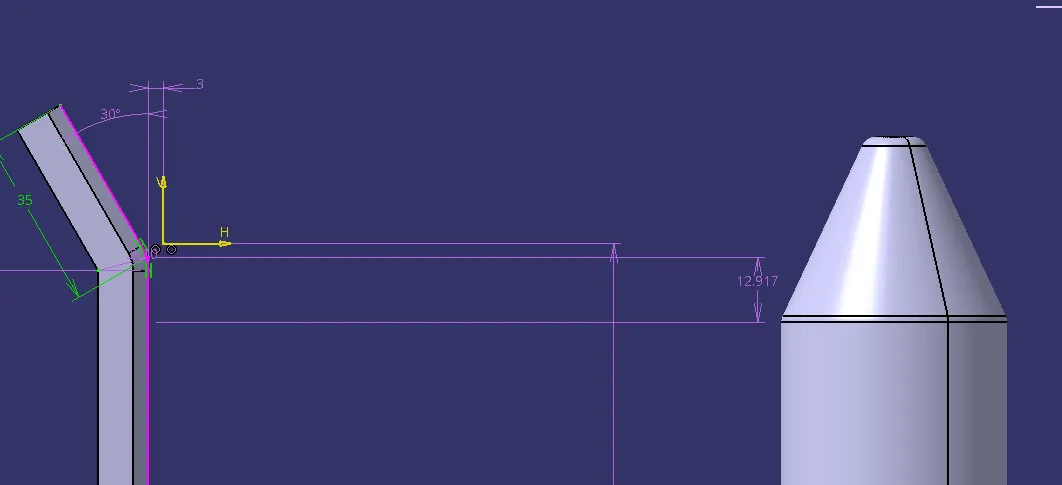
- The entry point/ top point of the rough locator must be 10mm-15mm above the panel surface.
- Rough locators should have adjustment in the direction of guiding plane.
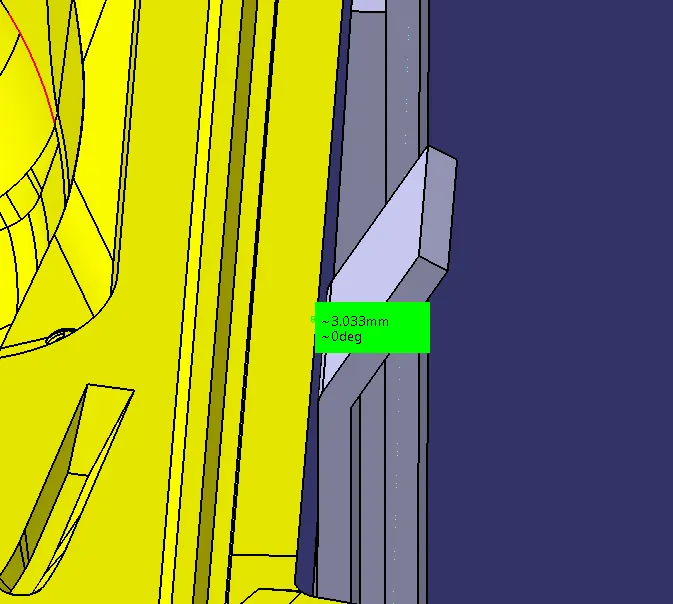
- 2 mm gap to be maintained between rough locator and panel at the time of design & we can provide adjustment of 5-10 mm in the positive or negative direction of guide plane.
- Rough locators can be rod type or flat type, depending upon the standards and other conditions.
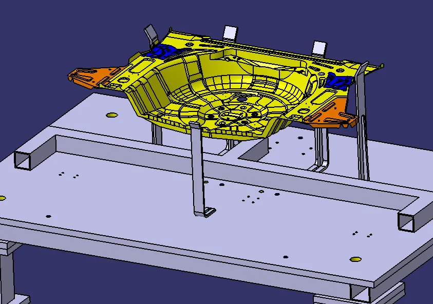
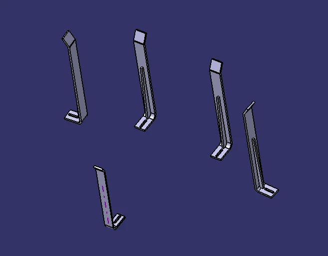
Rough locator 1
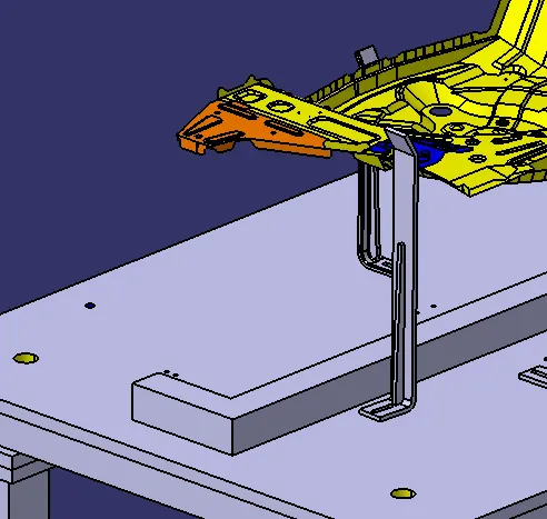
Rough locator 2 ( 2 nos)
Rough locator 3 (2 nos)
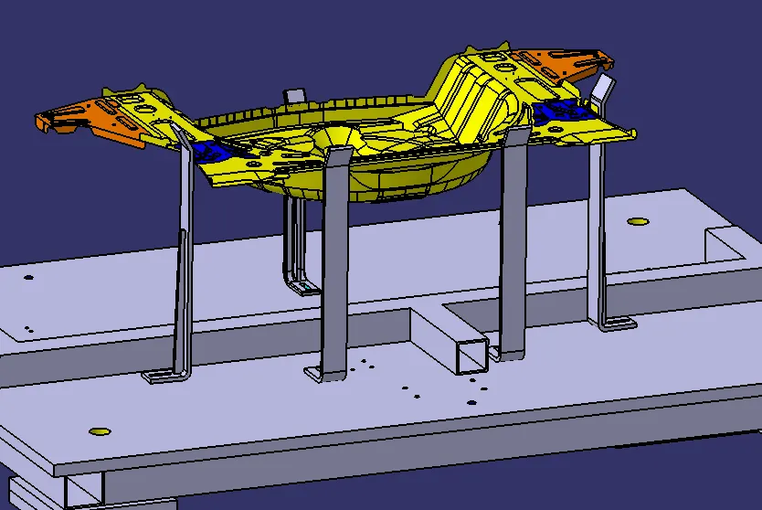
Full assembly
Full assembly with car panel
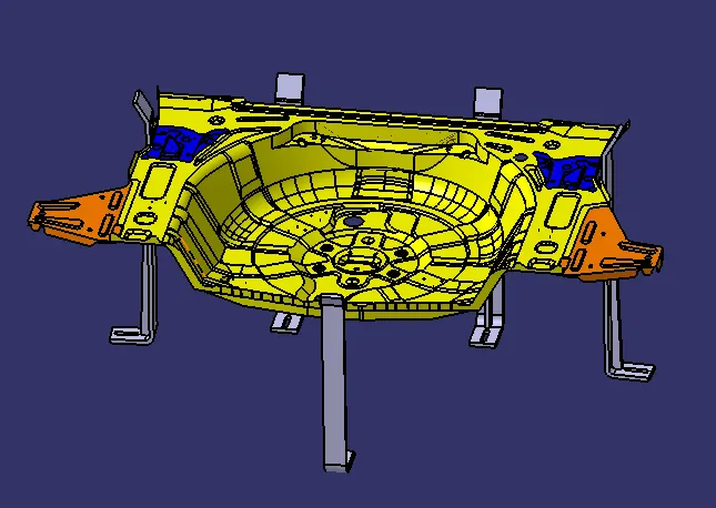
Design considerasion
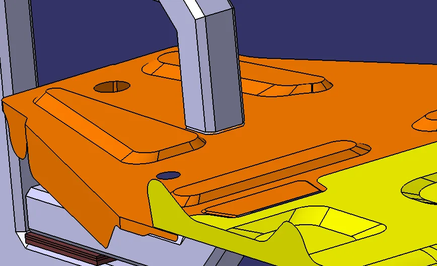
2-5m gap between car panel & rough locator
The entry point/ top point of the rough locator must be 10mm-15mm above the panel surface.
3D FINISH:
3D finish is a process where the design is being completely finish and to be ready for final simulation & 2d detailing.These is the process before sending the part for final simulation.
In these process the parts are checked for proper clearance and the nominality is also maintained. The machining sides of parts are applied with colour codes for representation.
Parts are checked for hole concentricity & size, standard colour codes are applied for holes and the fastners are also implemented. Renaming of parts is done for easy indentification in assembly.
Following points need to be taken care of while finishing the design:
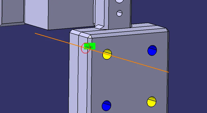
- Hole concentricity & hole sizes
- Machining area
- Nominality
- Holes colouring standard
- Pneumatic lay-outing
- Gaps checking
- Fasteners implementation
- Avoiding clash between different parts
- Mylars splitting as per panel profile
- Proper renaming of parts/assemblies as per the standard
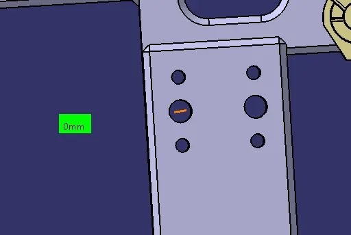
Check the hole concentricity & hole sizes for holes from all units
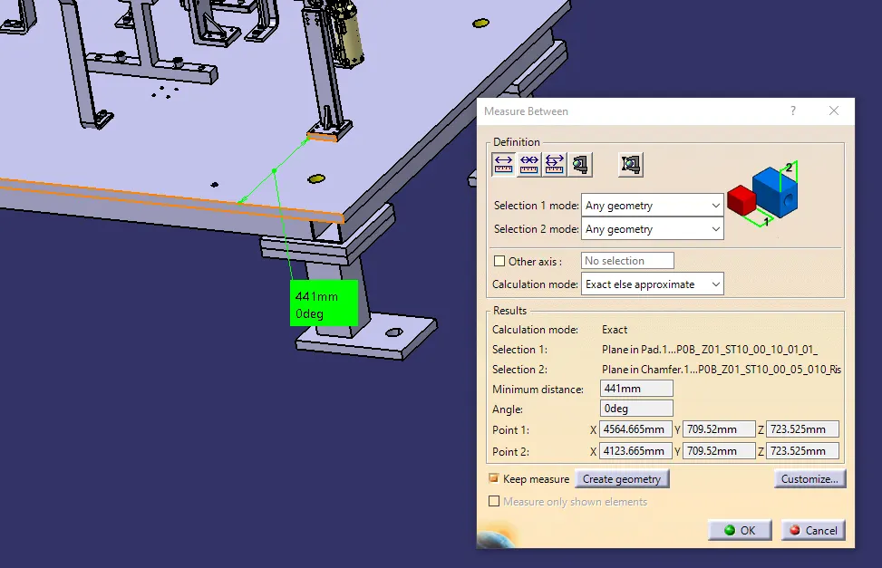
Maintain the nominality for all units
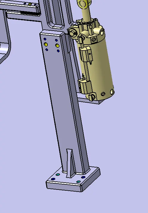
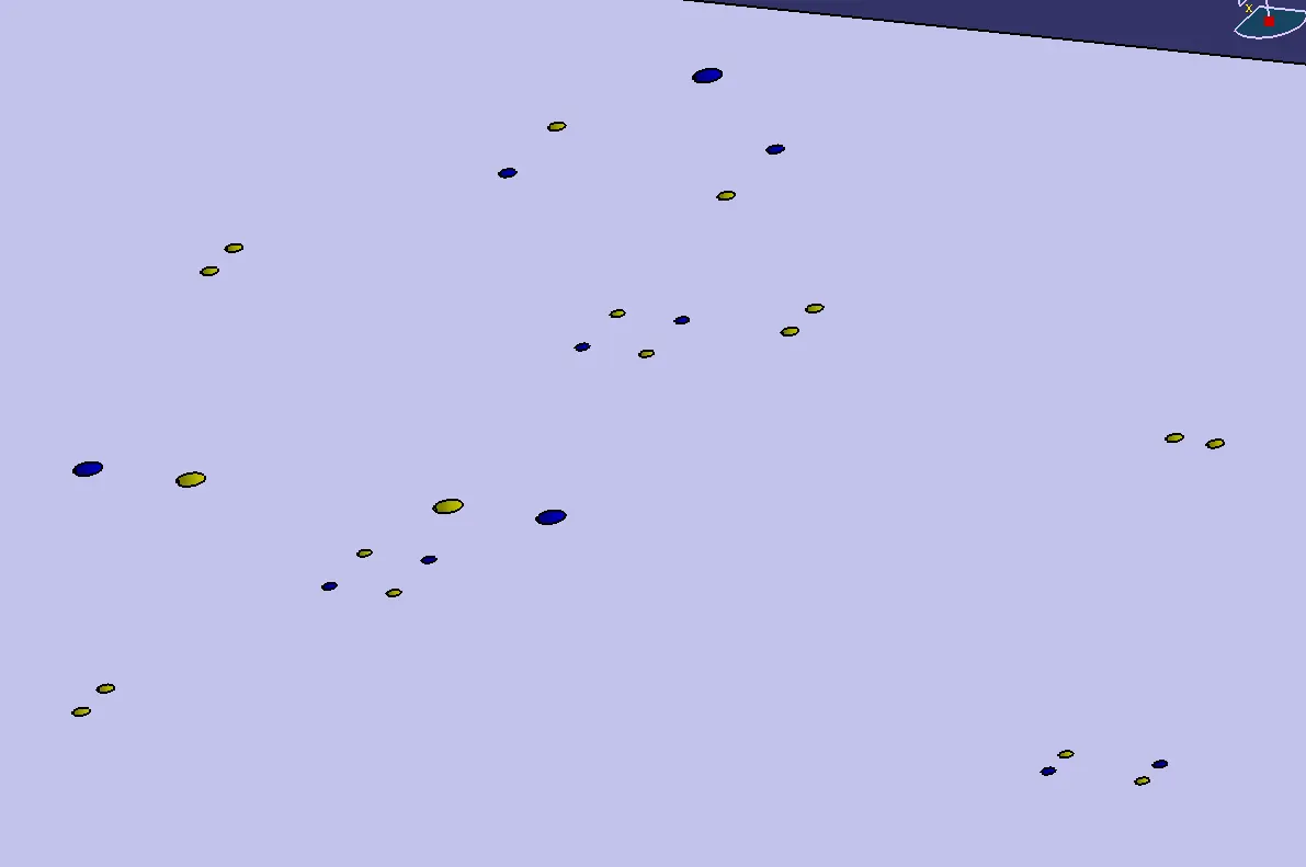
Apply proper colours to holes according to holes colouring standard.i.e Dowel hole-Violet, Open hole-Sky blue, Threaded hole-Yellow
Build a cable duct for pneumatic lay-outing
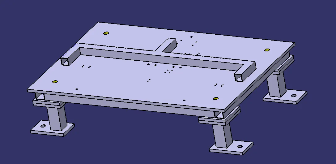
Check gaps between two components
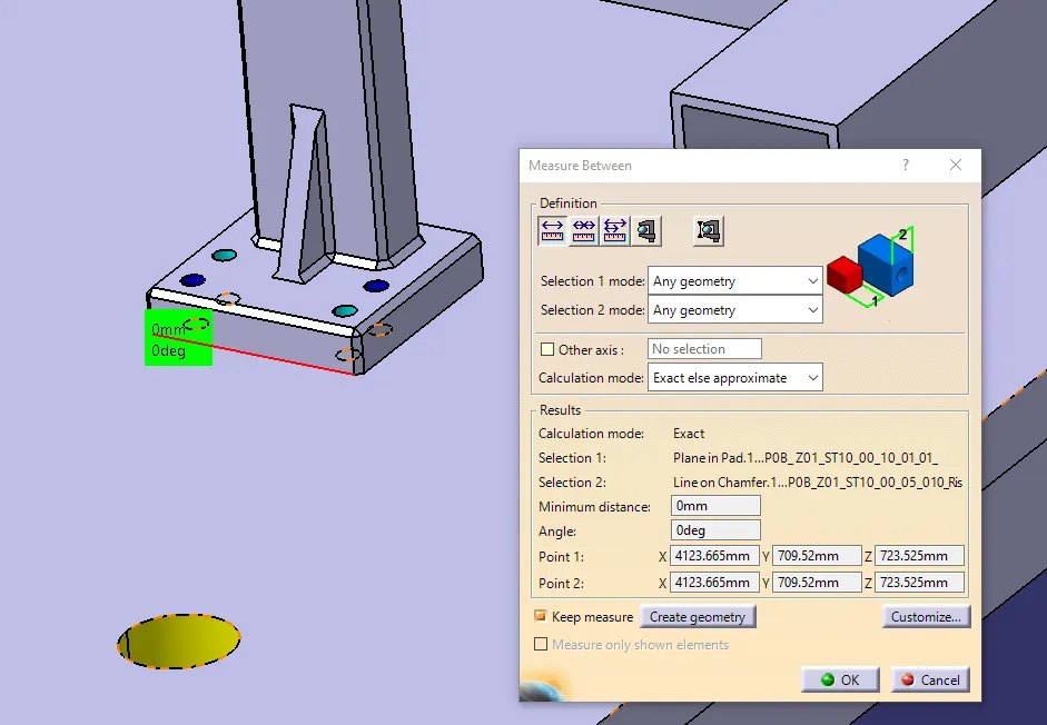
Implement fastners to fasten parts together and unit with base plate
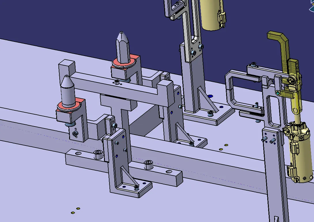
Avoiding clash between different parts
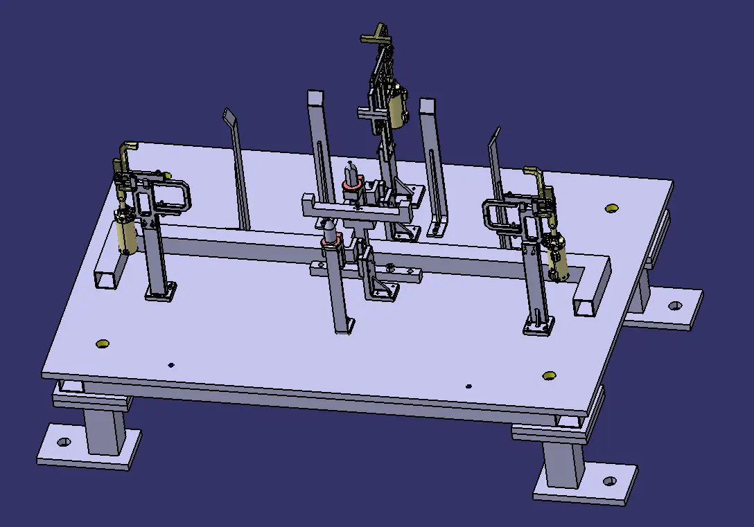
Mylars splitting as per panel profile
Proper renaming of parts/assemblies as per the standard
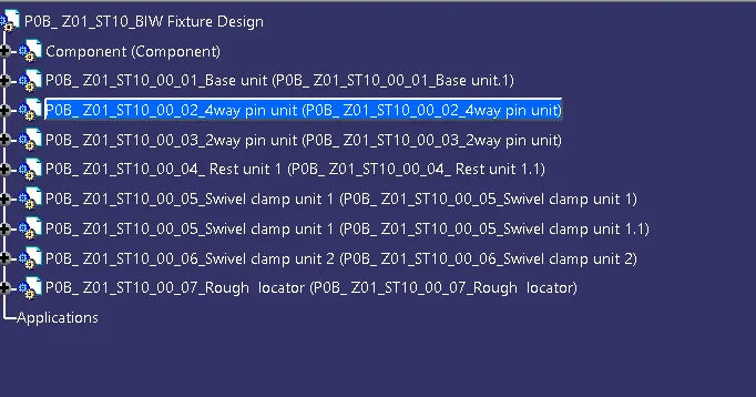
Tree structure
CONCLUSION
Thus the rough locators are provided and 3D finishing aare performed in the assembly design