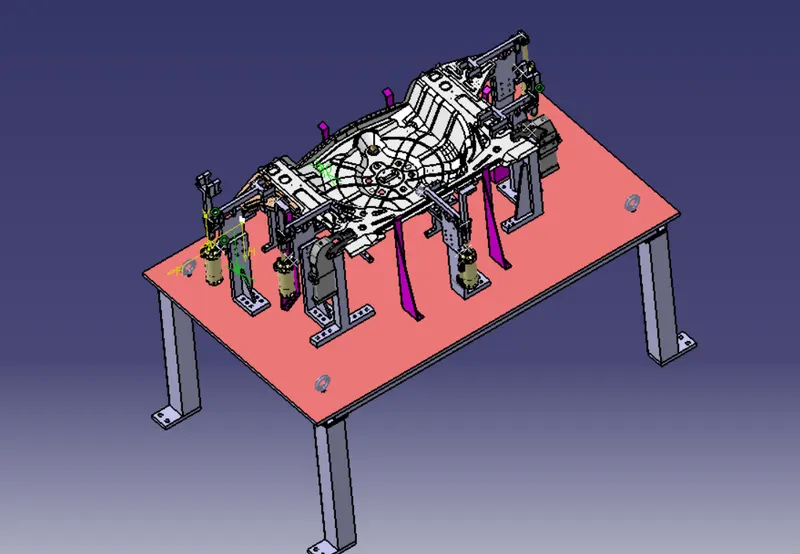
Week 8:- 3D Finishing Challenge 2
AIM:-
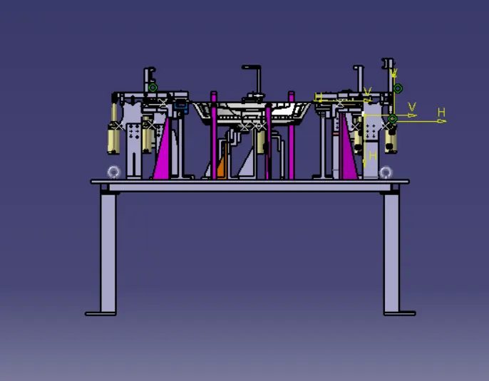
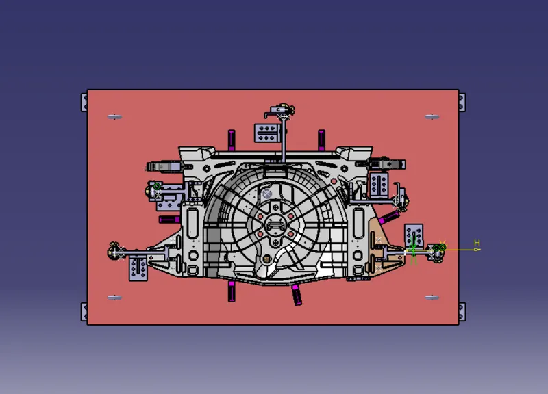
- Perform 3D Finish for all units of assembly design.
- create Rough locators for assembly.

3D FINISH:
The 3D finish is the process where design is completely finishing & to be ready for final simulation & 2d detailing .
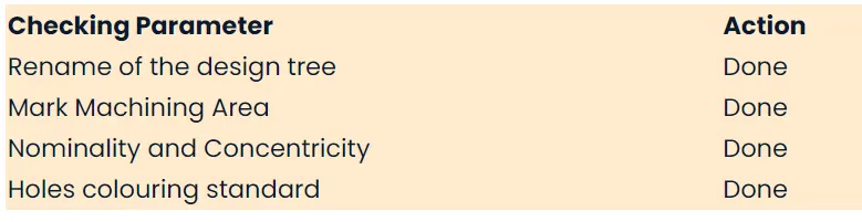
- In 3D finishing we finishing we perform and ensure the following points:
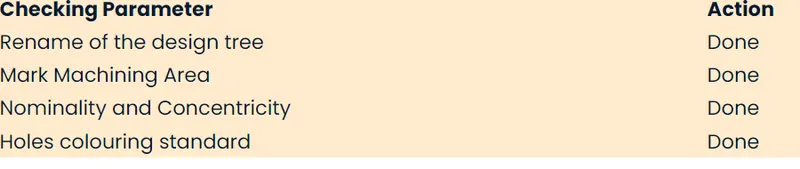
1.Hole concentricity & hole sizes:-All parts hole concentricity is checked & confirmed while finishing the parts.
2.Machining Area - The maching area in every part is detailed & the machining area is highlighted by using orange colour.
3.Nominality-All unit dimensios are maintained nominal to facilitate easy assembly of the unit .
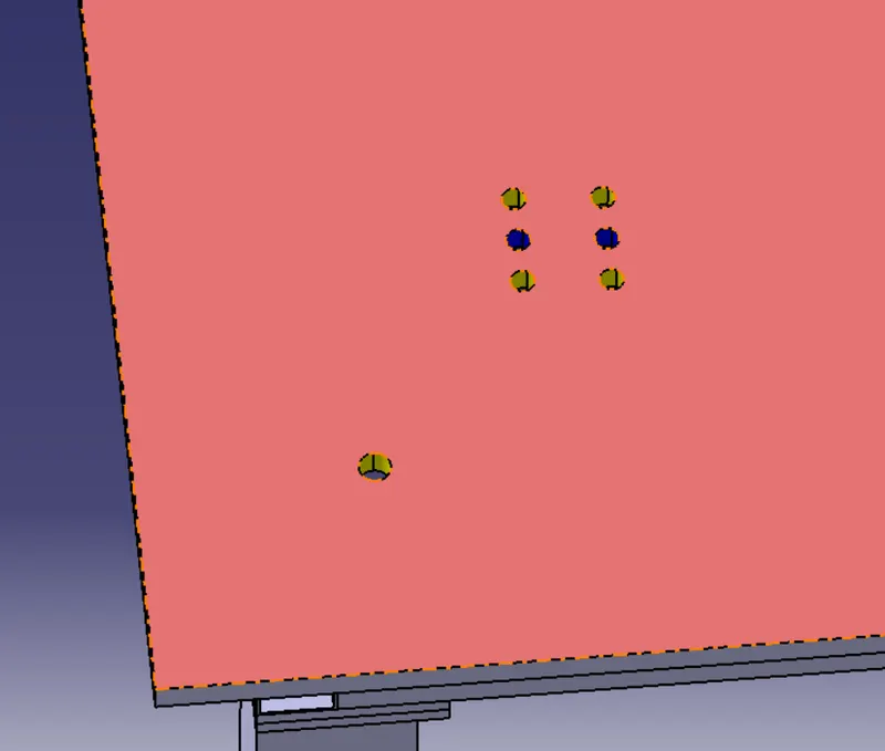
4.Hole colouring standard - Color code standard used in the 3d finishing
- Cyan - Simple hole
- Yellow - Thread hole
- Orange - machined area
- BLue - Dowel pin hole
4.Fasterners implementation - Fasteners are implementation in all unit as per requirement & load on the part.
5.Fastern implementation -Fastern are implementation in all unit as per the requirement &load on the part.
6.Avoid the clash between different part:-proper gap is maintained between parts to avoid the clash .
7.Mylor Splitting as per panel profile-Mylor splitting are confirmed while finishing the design.
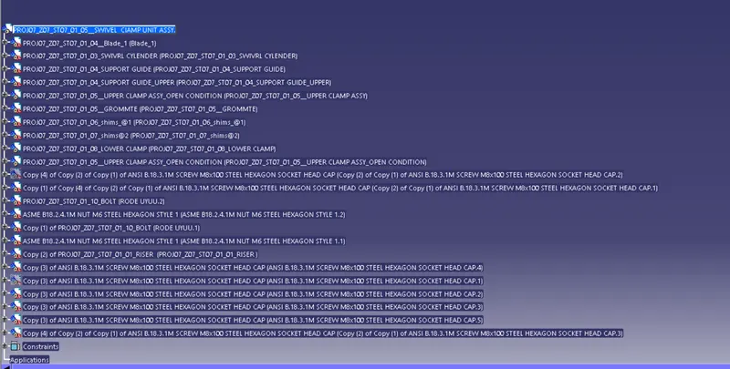
8.Proper renaming of parts / Assemblies as per standard -proper renaming of parts & assembly are done while finishing the design hence we can identify each & every part easily with a unique identification.
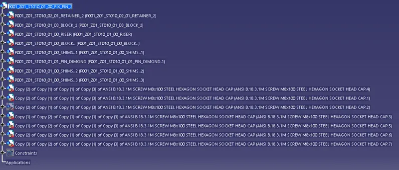
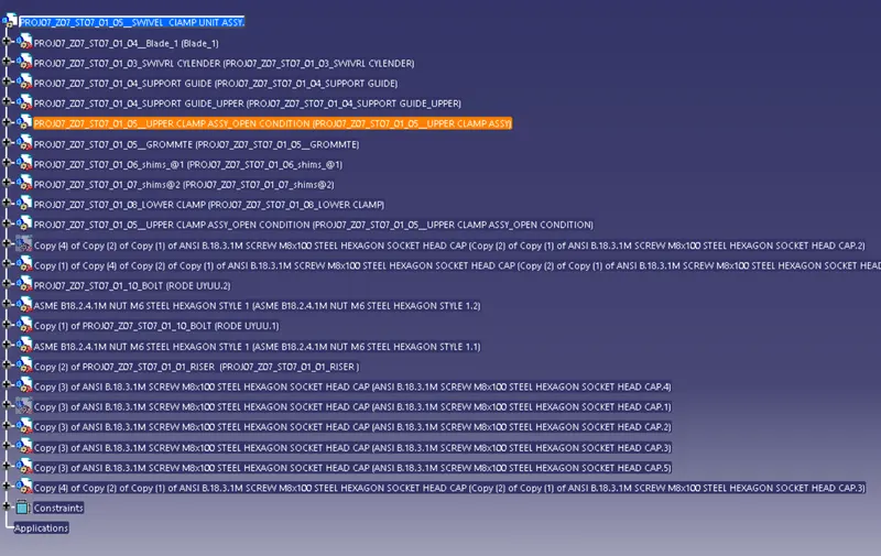
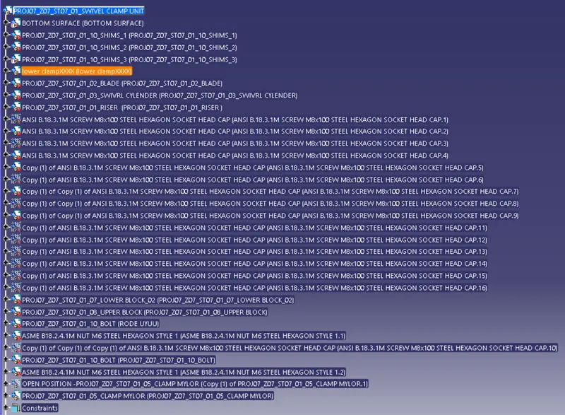
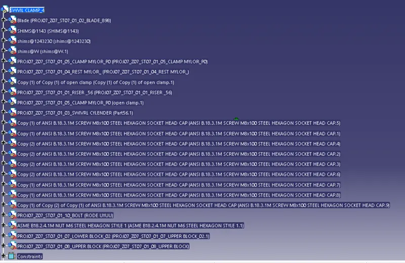
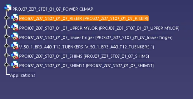
1.Renaming and Structuring of the design tree:
- Renaming of the design tree is done and structuring design tree in way that its simple to identification the units some units use multiple time those are easy to identify by its
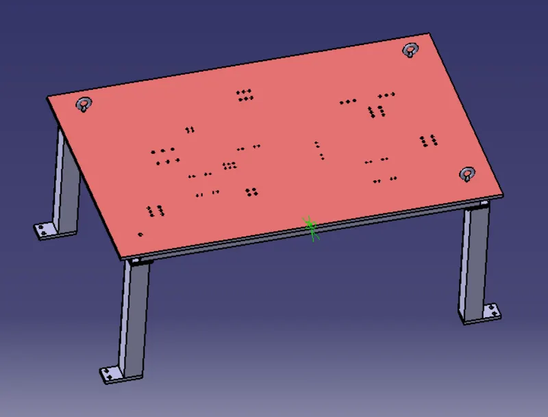
2.Base Unit:-
- Renaming of parts and structuring design tree
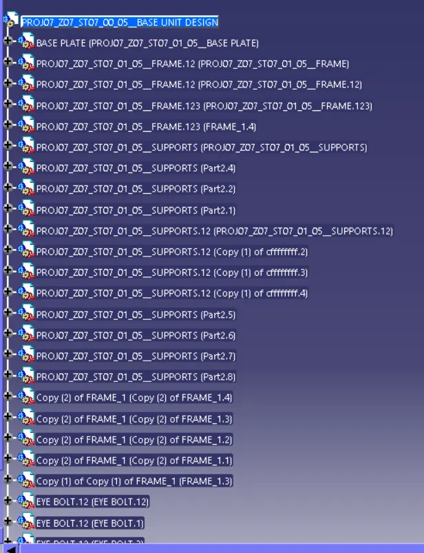
- Threaded hole and dowel holes making nominal and colour-coding are done so easy to distinguish holes.
- Threaded hole (Yellow), clearance hole (SKy blue),Dowel Hole (Blue),Machining surface(orange)
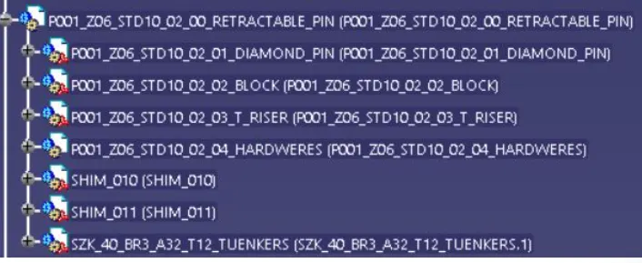
3 Retractable pin unit
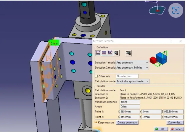
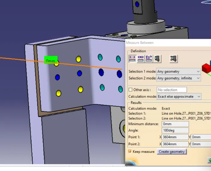
- Holes are make to the nominal and Concentric to each other.
- The open position of retractable pin is shown in yellow colour
- The proper butting of the two parts is done.
- colour coding is done as per the standards.
- structuring design tree renaming of parts is done.
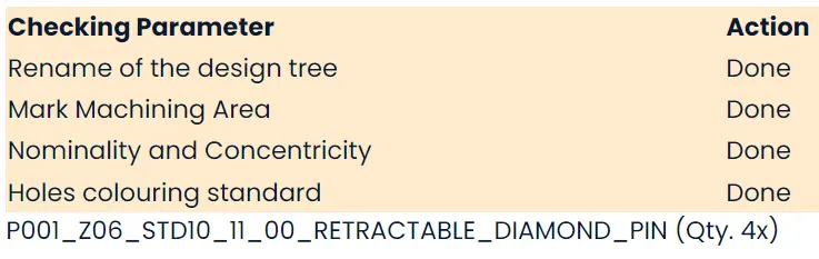
- Below are some images after 3rd finishing done on fix pin unit.
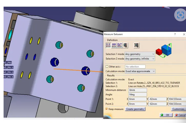
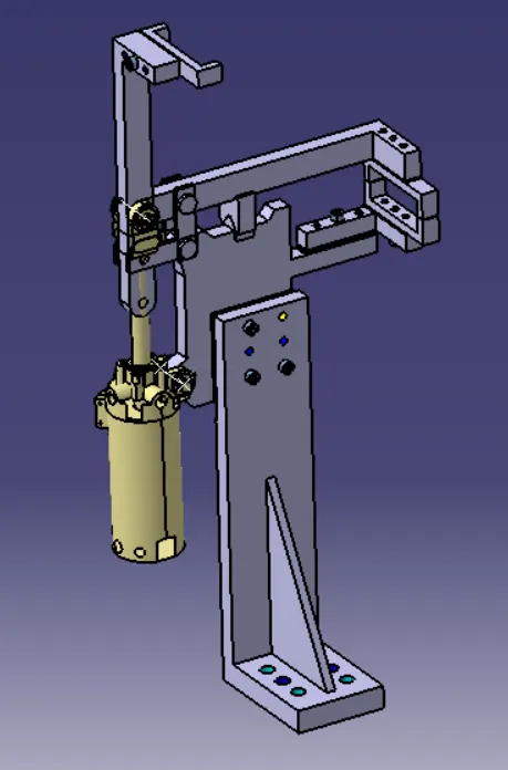
4 Swivel Clamp Unit
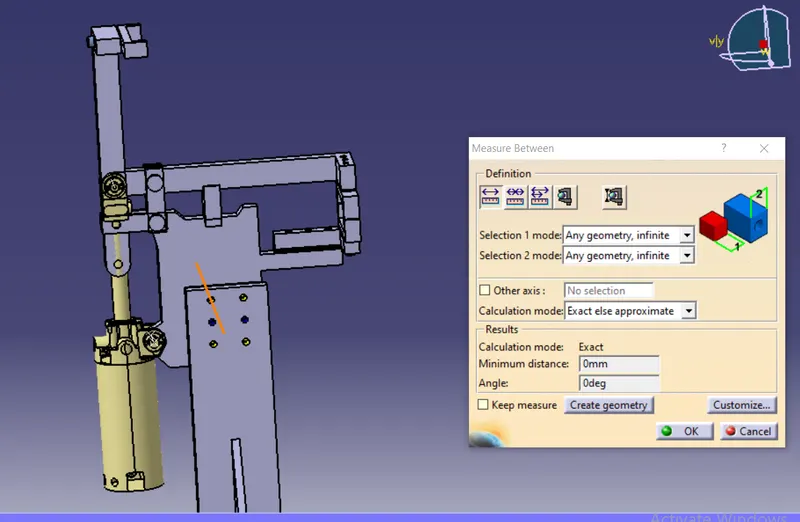
- Holes are make to the nominal and Concentric to each other.
- The proper butting of the two parts is done.
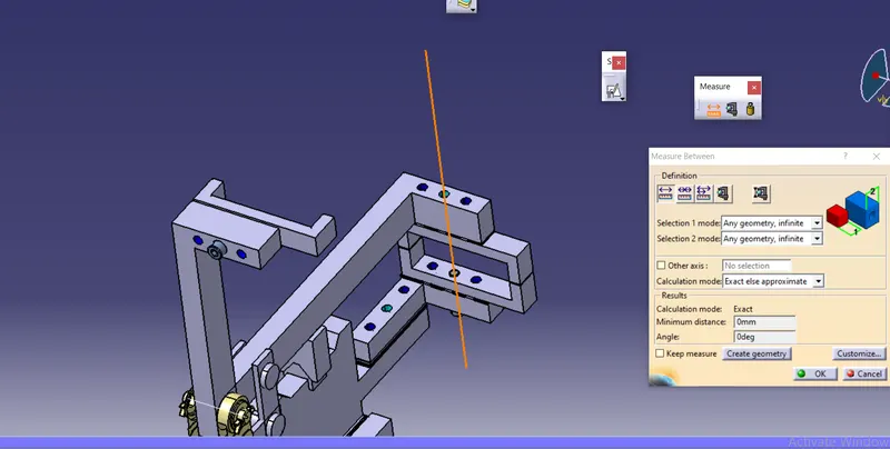
- Fasteners are implemented.
- Colour coding is done as per the standards.
- Structuring design tree renaming of parts is done.
- Mylar splitting is done.
- The open position is shown in yellow colour.
- Below are some images after 3d finishing done on swivel Clamp unit.
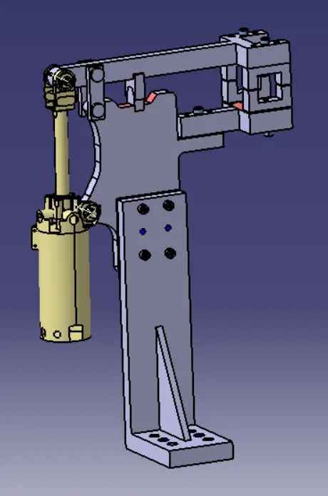
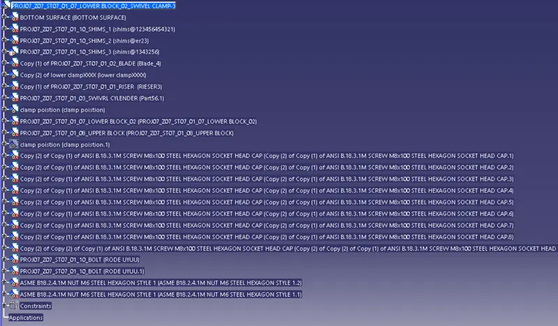
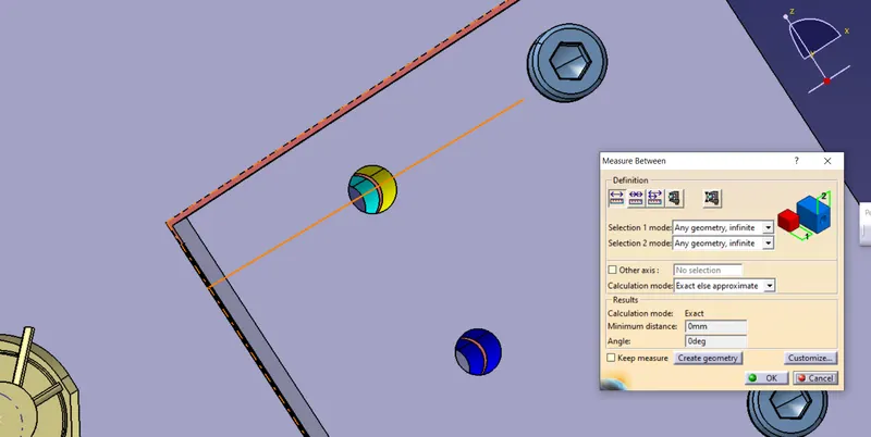
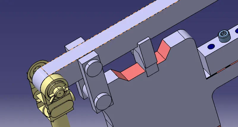
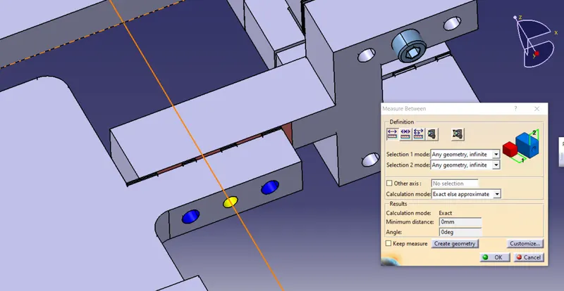
PROJ07_Z07_ST07_01_05__SWIVEL ClAMP UNIT ASSY.
5 Power Clamp Unit.
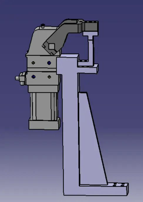
- Holes are make to the nominal and cocentric to each other.
- The proper putting of the two parts is done.
- Fasteners are implemented.
- Colour coding is done as per the standards.
- Structuring design tree renaming of parts is done.
- Mylar splitting is done.
- The open possition is shown in yellow colour.
- Below are some images after 3d finishing done on swivel clamp unit.
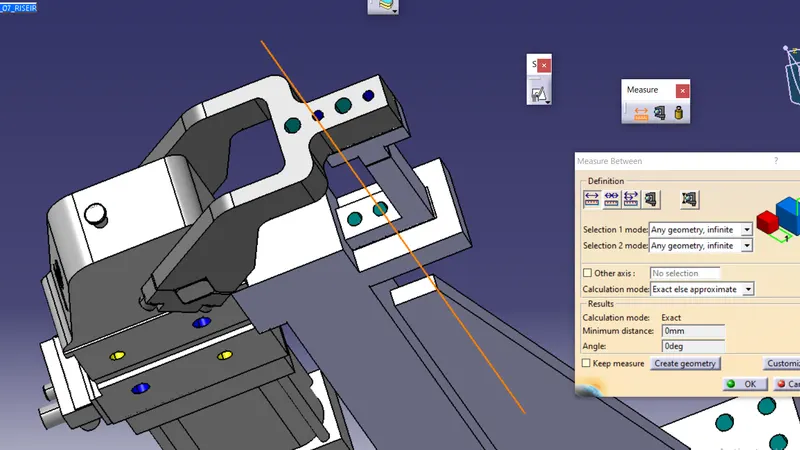
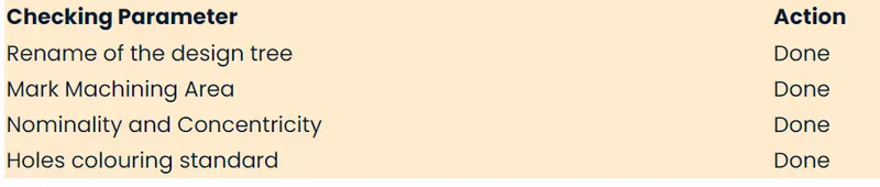
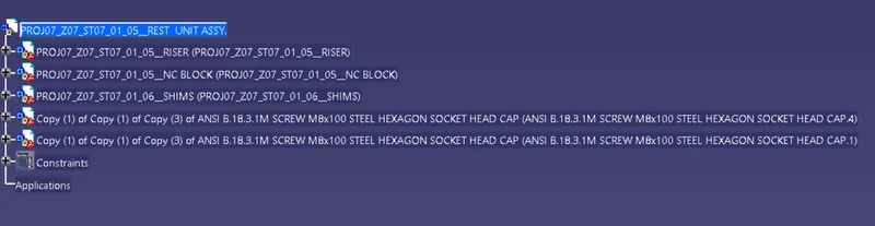
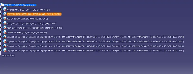
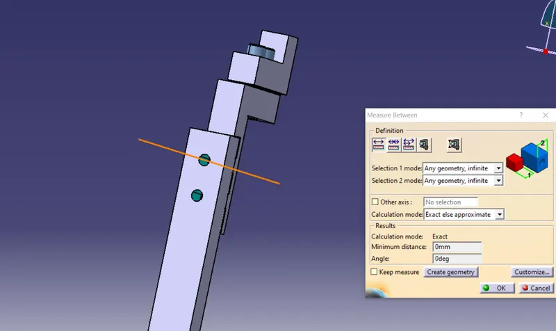
6 Rest Unit
- Holes are make to the nominal and cocentric to each other.
- The proper butting of the two parts is done.
- Colour coding is done as per the standards.
- Structuring coding is done as per the standards.
- Structuring design tree renaming of parts is done.
- Mylar splitting is done.
- Below are some images after 3d finishing done on swivel clamp unit.
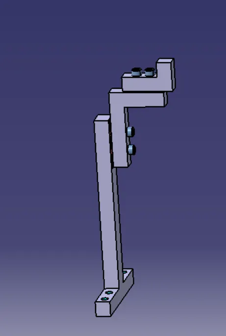
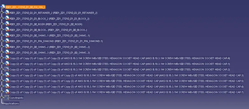

7 PIN CLAMP UNIT
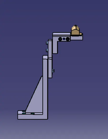
- Holes are make to the nominal and concentric to each other.
- The proper butting of the two parts is done.
- colour coding is done as per the standards.
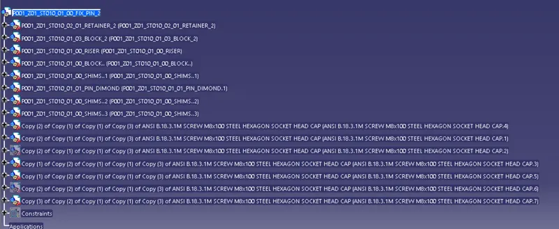
- structuring design tree renamingof parts is done.
- Mylar splitting is done.
- Below are some images after 3d finishing done on Swivel Clamp unit.
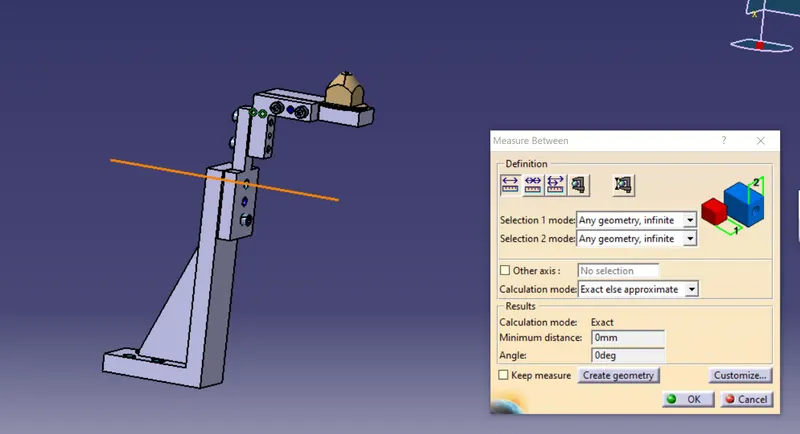
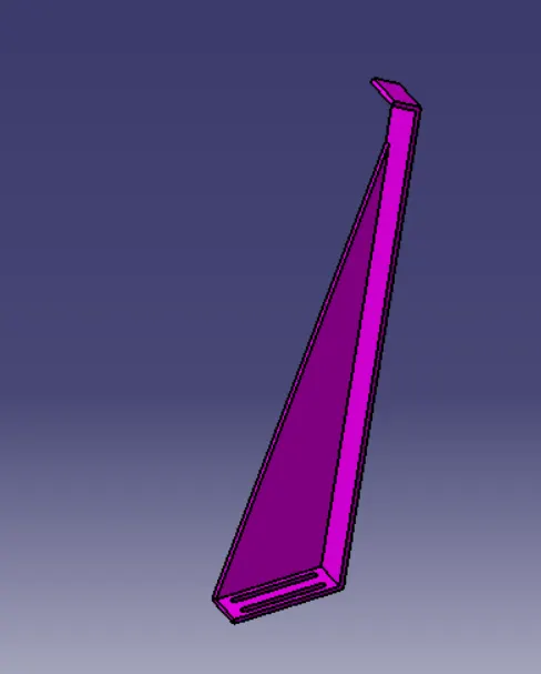
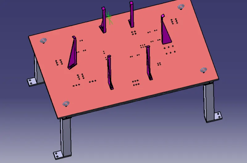
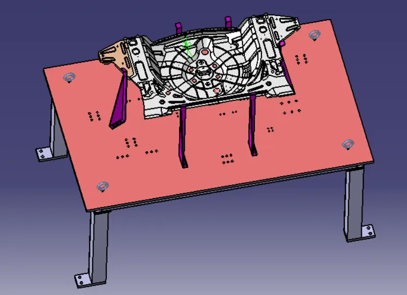
8.Rough Locator
- Provide locator in 4 direction.
- Menstion 0 mm gap between rough locator and panel.
- Here i use 6 rough locator as shown below.