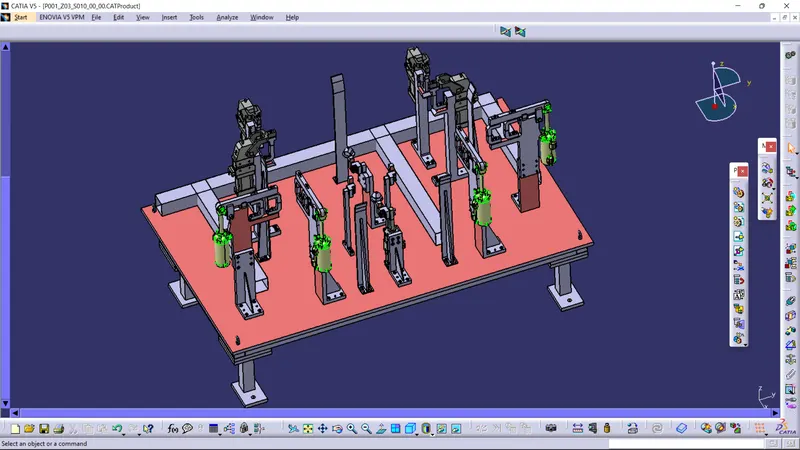
Week 8:- 3D Finishing Challenge 2
Introduction:
3D finish is a process where the design is being completely finish & to be ready for final simulation & 2D detailing Following points are taken into consideration while finishing the design
1. Hole concentricity & hole sizes
All parts hole's concentricity & holes sizes are checked for easy assembly while finishing the parts
2. Machining area:
The machining area in every part should be defined & the machining area should be highlighted by using standard color code Machining is to be done on parts to properly mount with mating parts. Machining only on desired faces reduces cost & save time also machining increases accuracy of dimension. So before going to simulation or detailing machining area should be defined.
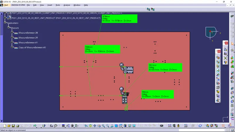
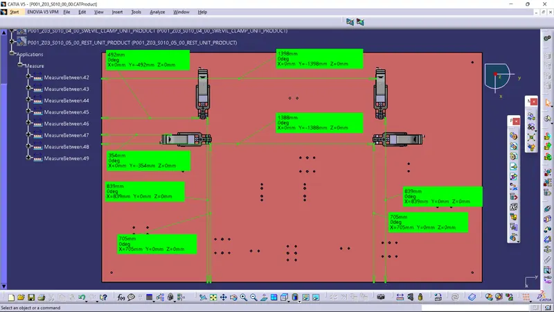
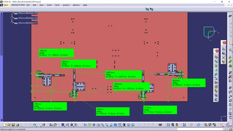
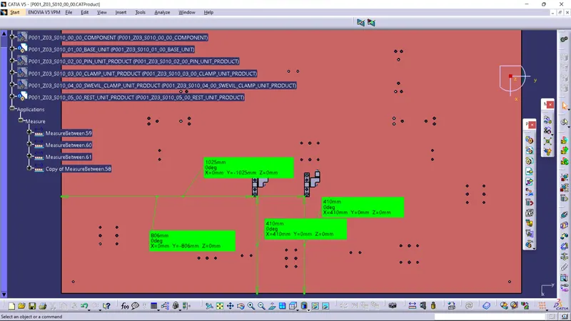
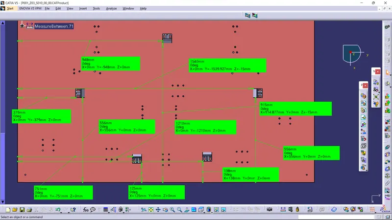
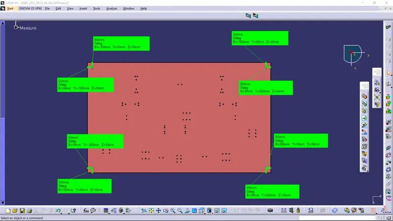
3. Nominal positioning of unit:
All unit's dimension should be maintained nominal to ensure easy assembling of the unit Pin unit are exception to this as they are primary locators and cannot change their location.
4. Hole's coloring standard:
In 3D finish holes coloring should be done to identify what type of hole it is? It depends on customer standard. Customer specifies color like
-Blue BLUE Color for Dowel holes
-Yellow Color for Threaded holes.
-Sienna Blue Color for Counter bore or Simple holes
-Pink/Cream Color for Machined area
5. Pneumatic lay-outing
Pneumatic lay outing is arrangement of different pneumatic pipes which work as an inlet to the pneumatic cylinder It should be done properly for proper functioning of the units
6. Gaps checking:
The gaps between the different units checked to ensure the proper individual working of different units
7. Fastener's implementation
Fasteners should be given in all units as per the requirement & load on the part
8. Avoiding clash between different parts
Proper gap should be maintained between units to avoid the clash between the different units
9. Mylar splitting as per panel profile
Mylar splitting as per panel profile should be confirmed while finishing the design.
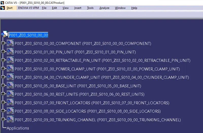
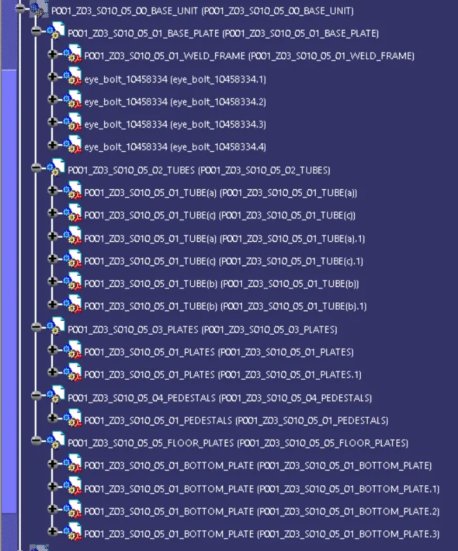
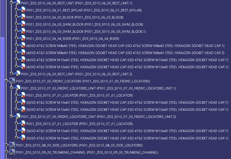
10. Proper renaming of parts/ assemblies as per the standard
Proper renaming of parts & assemblies should be done while finishing the design hence we can identify each & every part easily with unique identification
Checking the Nominality for all units:
Renaming the Components:
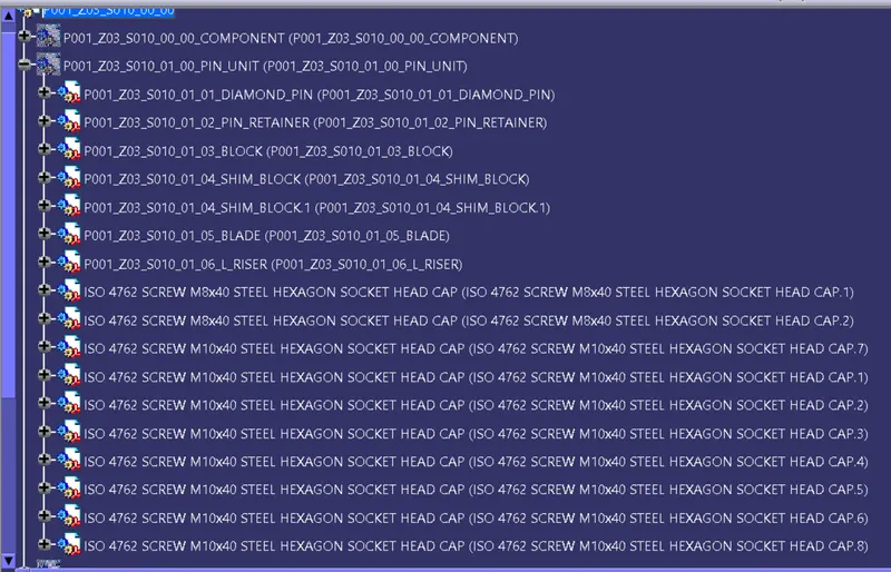
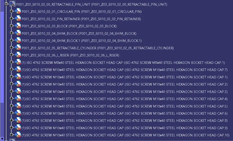
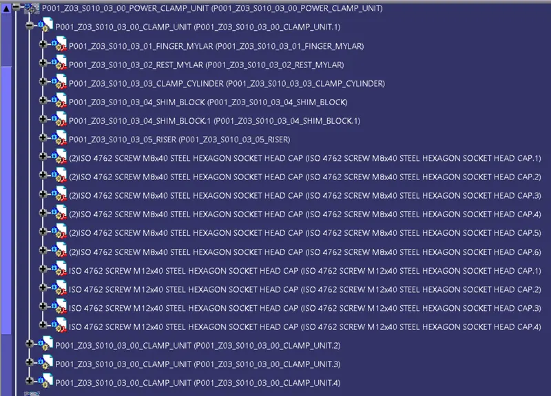
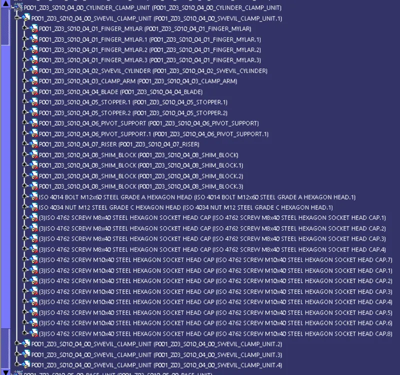
Components After 3d Finishing:
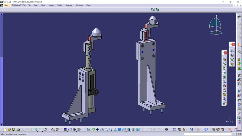
1. Pin Units:
2. Power Clamp Unit:
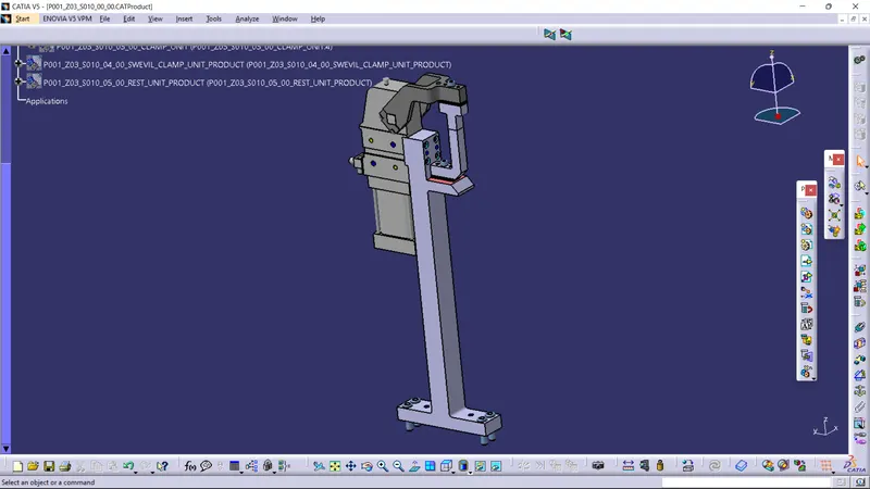
3. Swevil Clamp Unit:
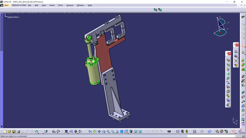
4. Rest Unit:
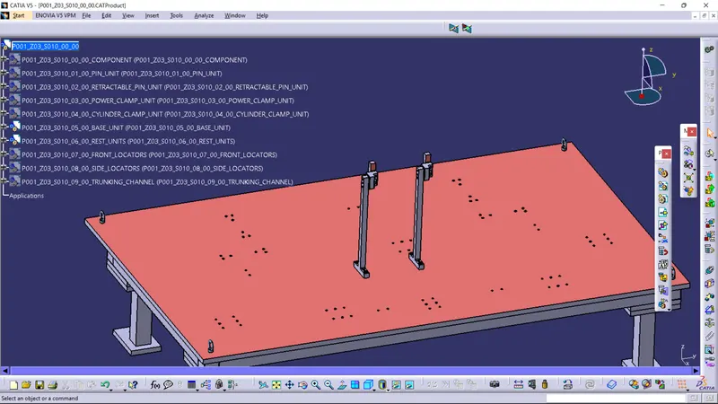
5. Base Unit with Pneumatic routing:
Trunk channel profile
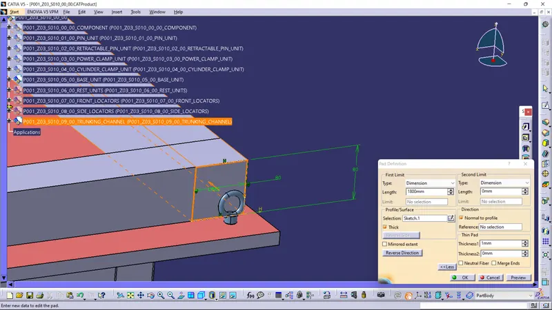
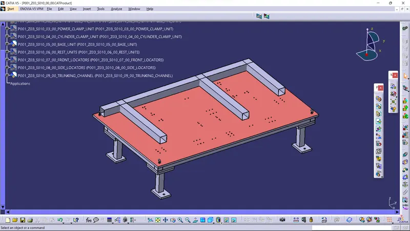
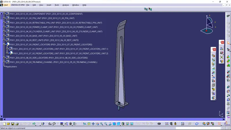
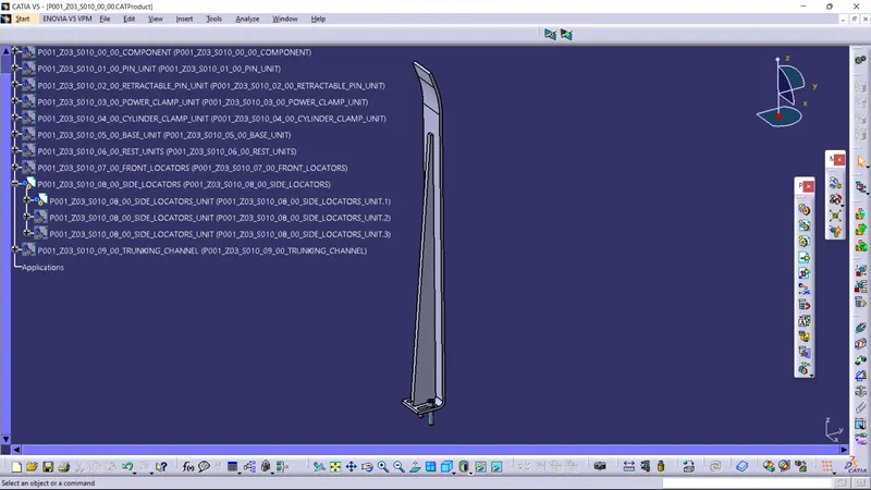
LOCATORS:
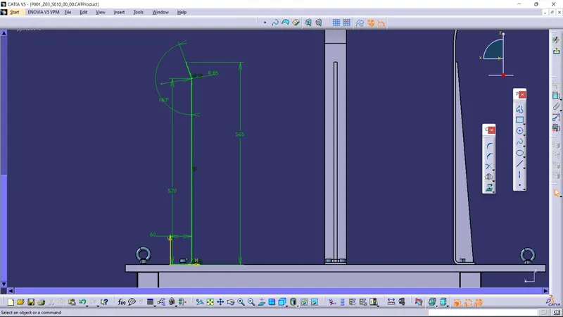
PROFILE OF LOCATORS:
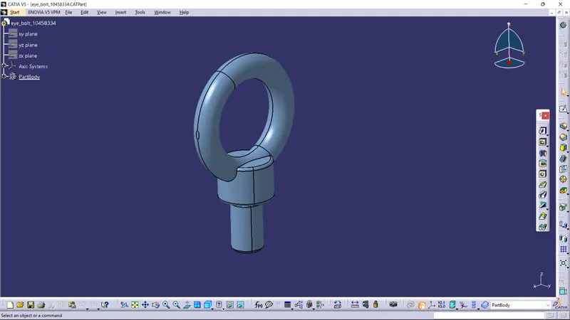
EYE BOLT:
A standard M10 eye bolt is used
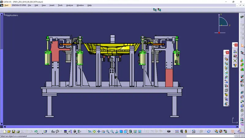
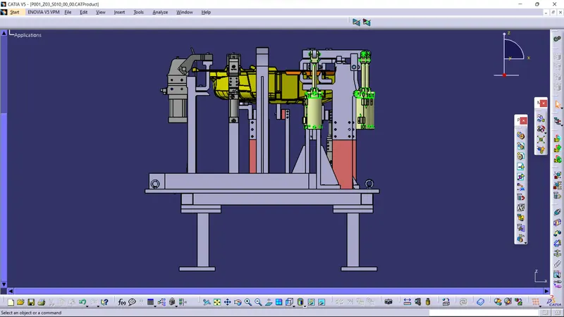
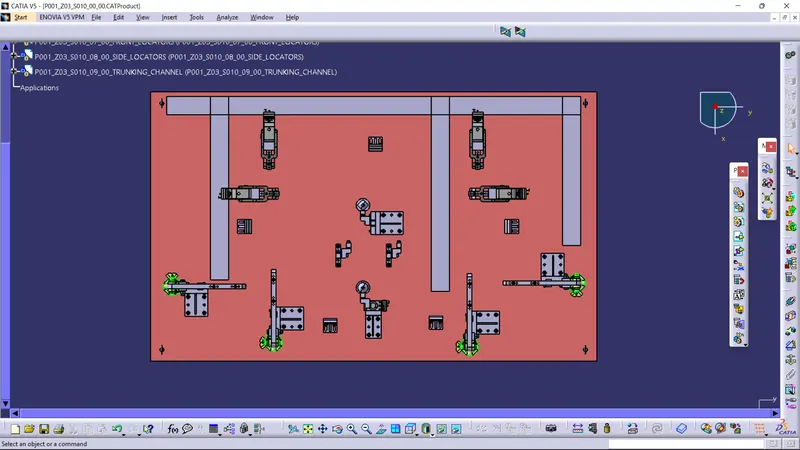
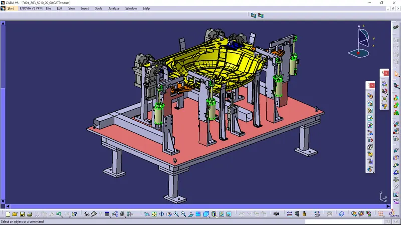
POSITIONING AND PROJECTION VIEW OF FULL UNIT:
FRONT VIEW:
SIDE VIEW:
TOP VIEW:
ISOMETRIC VIEW 1:
ISOMETRIC VIEW 2: