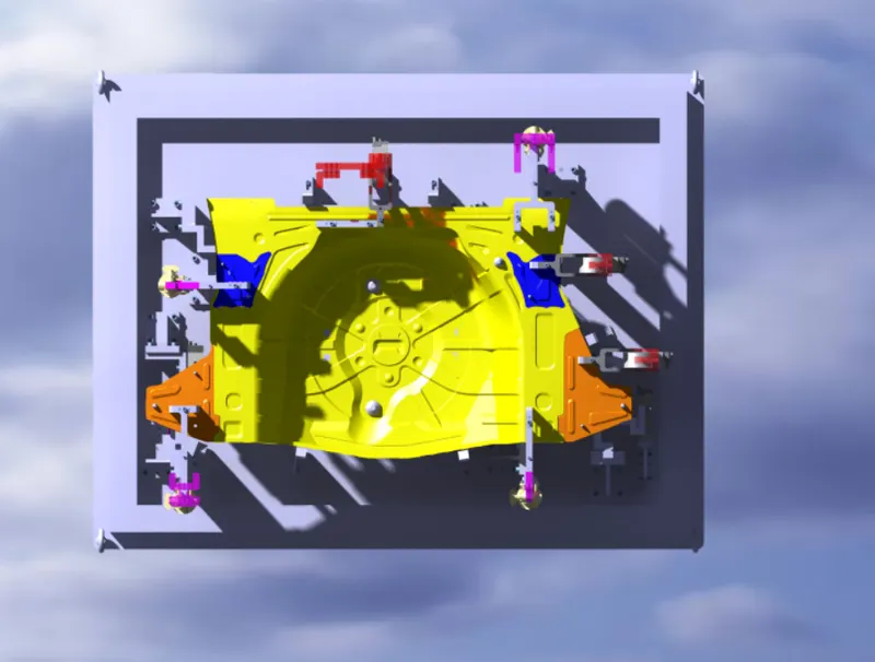
Week 8:- 3D Finishing Challenge 2
3D Finish:
- 3D finish is the process where design is being completely finish & to be ready for final simulation & 2D detailiting.
- While finishing the design the nominality of holes is checked which ensures the easy assembly of all the units.
- The hole concentricity & holes sizes are checked which ensures the easy assembly of different parts.
- The gaps between the different units are used to ensure the proper in working units.
- Fasteners are implemented as per the hole size & the standard color codes as per the customer requirements are applied to differentiate the type of hole whether ifs a simple hole, threaded hole or counterbore hole.
- Renaming the assembly & the part is done to give every part a different Identity. So everyone can identify in which assembly the particular part is going to be fit.
- After doing all these things the model is sent for to simulation department to Simulate the design with robots whether the gun is clashing or not & ID detailing.
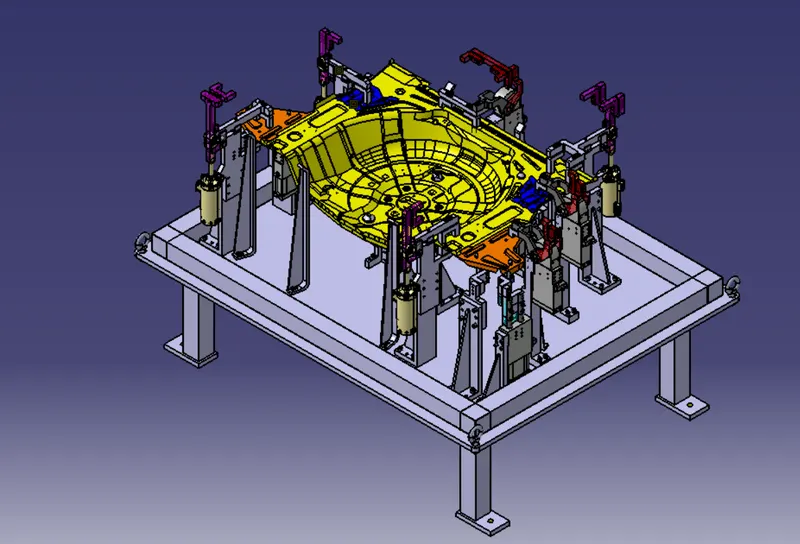
Rough Locators and its use:
- A rough locator isa part designed to guide the operator, to locate the car panel on to the pins accordingly. A rough locator can be of standard part or make part.
- Rough locators are used to help locate work pieces in the automation process. Locating refers to the desired location where we want the work piece to be sitting. when it is getting on either worked on either by a person, team, or a robot.
- Body part rough locators are provided to assist manual part loading to the tool.
- The following are general guidelines for rough locators:
- It is not required to finish cold/hot rolled steel for rough locator mounting. Use NAAMS standard rough locators when possible.
- If possible, do not place rough locators in positions that force the operator to lift and load, or unload the part over the rough locators.
- Rough locators must be designed with slots for ease of adjustment.
- Rough locators should have minimal part contact so that the operator can load the part to work location with ease. Excessive part contact may cause difficult part loading and unloading.
- Rough locators must never touch the part when it is nested or controlled by the primary tool locators.
- If the rough locator requires a unique design, use the design parameters for the standard NAAMS rough locator as a guide.
- A rough locator isa part designed to guide the operator, to locate the car panel on to the pins accordingly. A rough locator can be a standard part or make part.
- It is used to identify the correct orientation of the panel.
- It can be called as fool proofing method also. Because due to the rough locator the part cannot be loaded in incorrect position.
- The rough locators are set according to the angle of the respective panel hence part can only be loaded in defined orientation.
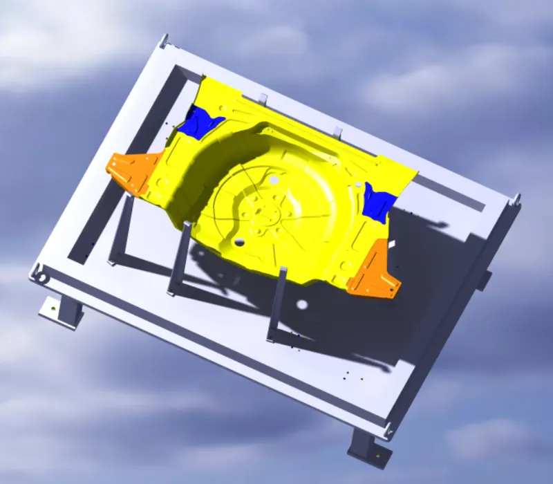
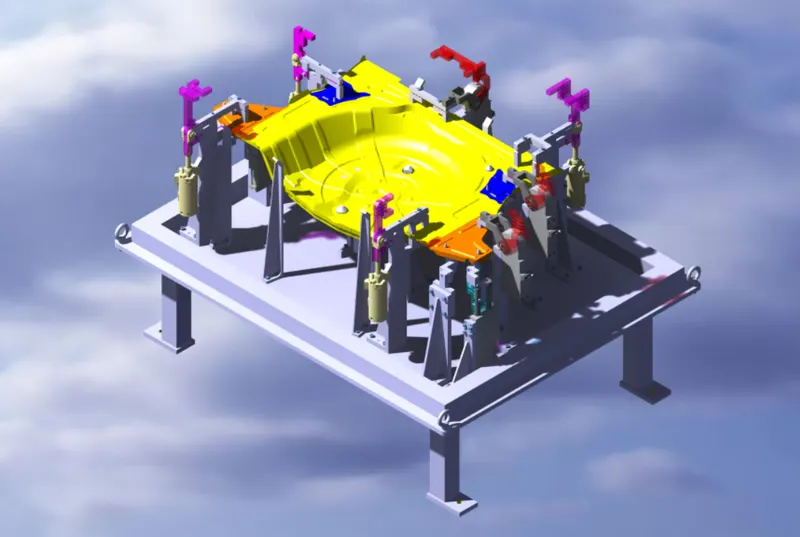
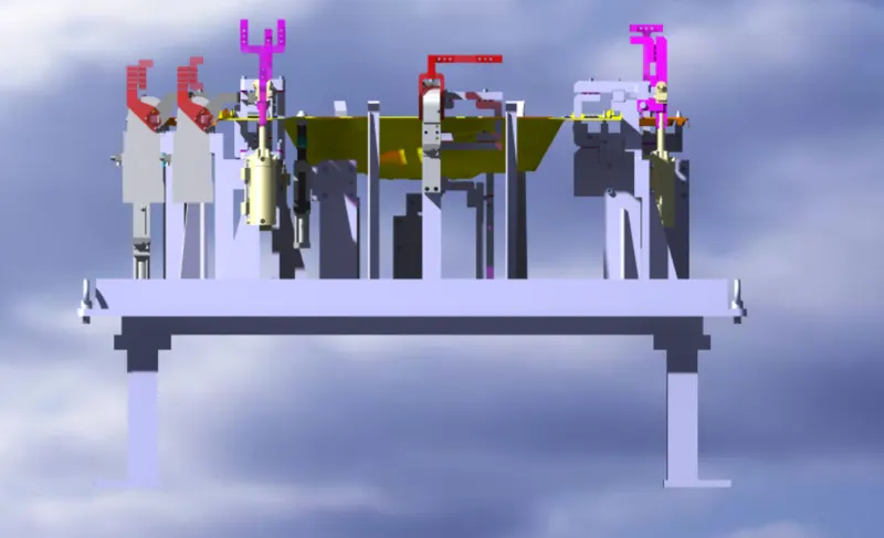
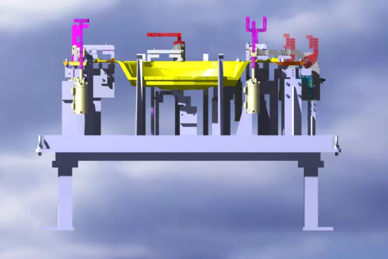
3D FINSIHING VIEWS;
ISOMETRIC VIEW;
FRONT VIEW;
TOP VIEW;