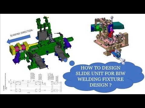
Week 3:- BiW Fixture Design Methodologies Challenges
1.What is Design Methodology?
Design methodology is the folowed by the different steps during the concept design stages in fixture design.
PURCHASE ORDER;
It is the order from customer to start the work.
INPUT FROM CUSTOMER;
It refers wat we required input from customer to start the work that all are
- functional requirements
- preferred standard components list
- car products
- layouts
- ergo data
- weld study
- standard detailing templates
PERCENTAGE COMPLETION CRITERIA;
It is followed the design stages and despatch stages of fixtures ,that means we convert the work stages in percentage of finishing stages.
DESIGN OUTPUT;
IN design out put we should give 3D &2D drawings of all each part in fixtures.
2.What are the inputs required from the customer to start designing a Fixture?
Basic input from customer are listed below;
- Functional requirements
- Preferred standard components list
- Car products
- Layouts
- Ergo data
- Weld study
- Standard detailing templates
FUNCTIONAL REQUOREMENTS;
what kind of functions done in the fixture or conveyors or racks.
PREFERRED STANDARD COMPONENTS;
There are different types of standards used depends in industry like TUNKERS,ZYTRAN,NAAMS,ABB,DESTACO.
wat are the standard parts we use like L block,pins,retainers ,risers
And also std components like cylinders,switch,sensors,slides and clamps.
CAR PRODUCTS;
In car products we need details of car parts that are
- GD&T
- CADdetails of car parts
- part list
- Clamp plan
- product assembly process sheet.
LAYOUT;
it gives the details of fixtures where gonna a place and other fixtures already where it placed and robots where it placed.
ERGO DATA;
Ergo data gives when a fixture to operate a manual operator need then only ergo data id required
Ergo data provide information of loading height and working safety zone of operator etc,
Ergonomics refers the study of human activities and behaviour.
WELD STUDY;
Wels study that gives the details of weld gun weld pionts and weld matrix.
3.What is the input we get from "Car Products"?
In car products we need details of car parts that are
- GD&T
- CADdetails of car parts
- part list
- Clamp plan
- product assembly process sheet.
GD&T
In GD&T provides information of
- Locating pins,rest clamps,dumpsand slide information of each staion.
- sequence of opening of clamps,dumos&slide stroke information
PART LIST;
In part list basically they gives the part name ,thickness of part &weld points
CLAMP PLAN;
In clamp plan provides the location of rest clamp,pins,dump etc,
CAD DETRAILS ODF CAR PARTSS;
In this they give the drawing of each parts of car product in both 2D or 3D in format
PRODUCT ASSEMBLY PROCEES SHEET;
In this they give like the flow chart how the product assemble from child parts to totally assembly.
4.What is the Clamp plan?
- In clamp plan provides the location of rest clamp,pins,dump etc,
- In clamp plan they give all the clamp details where to place and also that clamp x&y co ordinates in clamp plan details
- And they also given the origin co ordinates for design
- If any clamp have closer to weld spot we must clarify with customer to change the position of clamp in design
- For pins they also give the co ordinates and hole size of the product
5.What is the purpose of a Layout?
PURPOSE OF LAYOUT;
Layout gives the details of plant layout where we fix the fixture ,because to manufacture the fixture for that constrain space and height
In layout sheet informations are;
- FLOW OF PARTS
- STATION PITCH
- ROBOT STATIONS
- ACCESSORIES LIKE TOOL CHANGER AND TIP DRESSER
- SUB ASSEMBLY LINKS
- PLATFORM HEIGHTS
- LOADING\UNLOADING SEQUENCE \HEIGHTS.
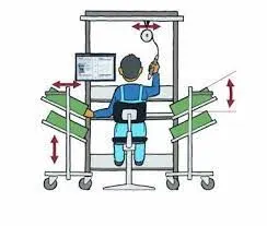
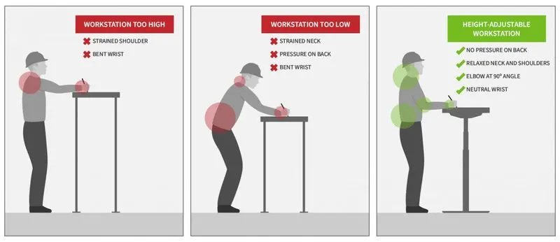
6.What is Ergo data?
- Ergo data gives when a fixture to operate a manual operator need then only ergo data id required
- Ergo data provide information of loading height and working safety zone of operator etc,
- Ergonomics refers the study of human activities and behaviour.
7.What do you understand by Weld study?
Weld study that includes
- WELDING GUN DETAILS
- WELD MATRIX AND WELD POINTS
Wels points are classifed
- GEO WELD POINTS
- RE SPOT WELD POINTS
Weld gun details we know the exactly wat kinf od weld gun we use for that particular operations and type oof welding operation we gonna done
weld points are nomally represented in the form of sphere shape
After the geo wled only re spot weld will happen
In drawing it self they given the weld points where we do spot weld in that particular stage or operations
8.what are the criteria for percentage completion in the designing stage? Explain it in detail
Precentage completion criteria is following the designing stages and dispatch stages of the welding fixture
0-25% - INPUT AND CONCEPT DESIGN
25-40% -CONCEPT APPROVAL AND SIMULATION CHECK
40-85% -DESIGN FREEZING AND DETAILING
85-100% -CHECK AND FINAL DESPATCH
In that 0-25% we must garther input for desgin in customer and finish the assembly drawing of the fixture and concept of the overall fixture
After thaat we semnd ur drawing to approval process and simulation sheck by cmm to ensure co ordinates and location of clamp wit the reference of given by customer they ur project completes 25-40%
Then everything cleared and ur design get approved we should do the detailing of the fixture to manufacture after finished this we achieve 80% of ur project
After everything completed manufacturing we should with drawing the fixtures by using CMM to ensure the fixture units are in the right co ordinates and we dispatch the fixture to customer to finish the project 100%.
9.Brief about "Output" in design?
The output is 3D model and 2D drawings of the tools
IN this we use different tools that are
- UNITIZED TOOLS
- NON UNITIZED TOOLS
UNITIZED TOOLS are bacisally required two types of drawings
KEY SHEETS -An inderx of units and their placements on the tool base
LAYOUT SHEETS -A detail drawing of individual units to include all other components
NON UNITIZED TOOLS
Tools that can be stand aloneand can be detailed completely in the layout sheet
In output design drawing we should the each units numbers and name in the drawing and also mention the material name and code
The output should compile following point;
- Approve standard components are to be used wherever possible
- design must be as simple and economical as possible
- Design must comply with all current safety and ergonomic requirements
- Design must provide for controlled and free handling of product
- Adequate error proofing provision must be incorporated in to each design by providing proximity switches,rough locators etc,
- The weight of the moving parts must be kept to a minimum while maintaining maximum strength
- frames and structure are to be simply and sturdy
- Design clearance and accessibility for routine maintenance and service
- motion control must be considered on any moving equipments
- designer is responsible to validate clamp and all weld guns
10.What do you understand by structuring a design tree? How does it reduce errors during the design process?
- Structuring a design tree implies to a process where all the assemblies and parts are named in a specific standards
- different customers have different set of standard to structuring a design tree
- it is an important process which helps us to identify a specific part or assembly as to which project, tool or unit ,it belongs to
- This help us to avoid errors during design study ,manufacturing, assembly inspection etc,
- if the parts or asssemblies are not named properly or the design tree is not structured properly ,it will create confusion to understanfd the design and may creaste major possiblilities of making an errror
- Naming of a fixture or a unit or a part gives thee information as to which project ot zone or assembly do they belong
- It can help us to identify the quantity of items of same type or different types that are being used in an assembly
- In structuring the design a tree we must provide a name of each every part in the fixture
- It should not be repeatetive and give a name depends on the part number and fixture name or number
- If we follow this we reduce the errors majorily
- In detailing we should write the name designed part by manually first after that only we mention the std parts wat we used in fixture corrrectly
11.What are Units? Mention 5 types of units.
In fixture there are many types of units we used to locate the workpiece or clamping the work piece in fixture without any movement for that we using different units
In one fixture there are many units to be attached
Types of units
- simple units
- complex units
siimple units various types depends on working method;
- REST UNIT
- FIXED PIN UNIT
- RETRACT PIN UNIT
- ROUGH LOCATOR UNIT
- SENSOR UNIT
- BASE UNIT
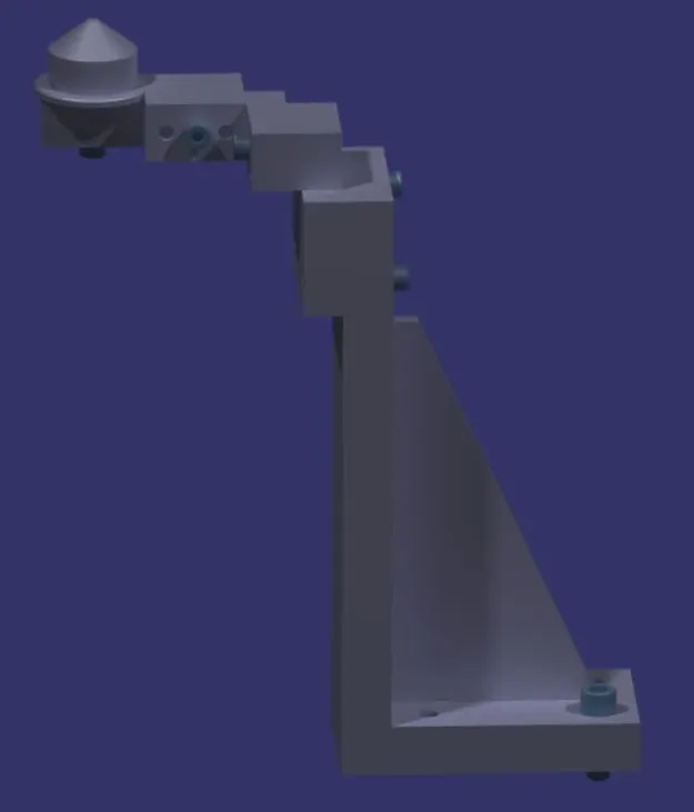
12.Describe Fixed Pin units & their purpose?
Fixed pin unit define the unit without any moving parts that can be fixed in the base plate of the fixtrure
the unit only to locate the panel by using pin
PURPPOSE OF FIXED PIN
fixed pin unit is a unit is designed to locate the car panel by using locating pins
In fixed pin unit we use both round and slot locating pins
fixed pin unit is used to locate the car panel without any rotational and up and down movement
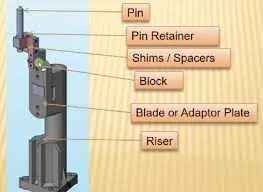
13.What are the different parts of a fixed unit?
There are different parts to be used in fixed pin unit;
- LOCATING PIN
- PIN RETAINER
- SHIMS/SPACER
- BLOCK
- BLADE
- RISERS
14.What is the purpose of making a Rest unit & describe its parts?
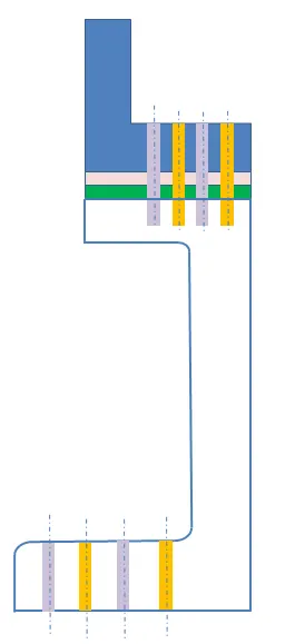
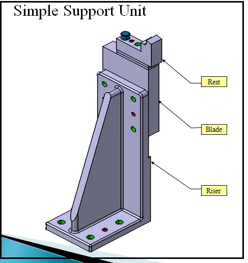
Rest unit is a unit designed to rest or support the car panel using NC blocks or mylars r orest
rest is used to support the car panel without any clamp r pins
This unit blades risers are the standard parts only mylars to be manufactured
Rest pin units are easy to design
This units are used to only support the car panel to arrest the down ward direction only
Rest pin are different parts
- BLADE
- RISERS
- SPACER
- NC BLOCK/MYLARS
15.What are the basic fundamentals to design a Sensor unit?
FUNDAMENTALS OF SENSOR UNIT DESIGN;
- Every single loose panel which are deing welded in a tool should be sensed
- Each panelshould be sensed by 1 to 2 sensors depend on the size of panel,preferred to be in diadonal opposit ends of panel
- Every sensor should be mounted in a 3 direction adjustable way in general
some major sensor mani=ufactures are IFM,SICK,OMRON,pepperl-fuchs etc,
Types of sensors used;
proximity sensors
LASER sensor
photo electric sensors
16.What is a Rough locator unit & what are the basic fundamentals to consider while designing it?
A rough locator is apart designed to guide the operator,to locate the car panel on the pins accordingly.
A rough locator can be of standard part or make part.
FUNDAMENTALS OF ROUGH LOCATOR DESIGN;
- Rough locators should be placed at the edges of the car panel,which it has to guide
- rough locators has to be placed in the same angle of the car part edge with a minimum distance of 2.5mm from the edge of the part
- rough locators should guide the panel in pin arresting direction
- rough locators sshould start guiding the panel before 10 to 15mm to the start of the pin engegement
- rough locators shouold be designed will entry angle of the car part entry
- rough locators should be designed with two slots to mount for easy adjustments
- the slot should be in the direction of car part guiding
17.What is a Base unit and describe it's parts?
A base unit is a unit designed to mount all the other units of the tool like clamp unit,pin umnit,rest unit etc, also othe parts necessary for a tool like pneumatic valva box , trunking cable path willl also mounted on the base unit
Some pasts of base units;
- BASE PLATE
- VALVE BOX
- MEASURING HOLE COVER
- EYE BOLT
- PEDESTAL
- TRUNKING CHANNEL
- WELD BARS
- FLOOR PLATE
18.What is a Dump Unit and what are its functions?
Dump unit is a unit to assemble the component which have certain constrain or geometrical constrain
Functions;
Dump unit is very complex to design
dump unit contains pin unit,retract unit ,rest unit,clamp unit are there
Dump unit functions with the help of dump cylinder
dump is very rare to use which the part have more constrain then only we prefer dump unit
19.What is a Slide unit? Mention where Slide units are commonly used.
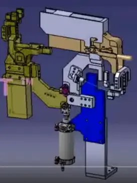
Slide unit is a unit desgin the fixture which has more units to perform alternatively we use slide units
slide units are mostly used where the fixture have more operations in same places we use slide units
slide units parts are;
GUIDE RAIL
SLIDE CYLINDER
GUIDE BLOCK
PISTON LOCKING UNIT
SENSOR UNIT
STOPPER BLOCK