Week 8:- 3D Finishing Challenge 2
Aim: To perform 3D finishing on the fixture assembly and adding rough locators wherever necessary.
Introduction:
At this stage the assembly is checked at various points for correct positioning. The concentricity of all the holes is checked. The assembly is checked for clashing with weld gun, if a clash is detected, the concerned fixture is moved to a better position. Surfaces that need to be on the same plane are checked. Fasteners and shims are added at appropriate positions.
Various holes are color coded as standardized for the project. The surfaces that need to be machined are indicated by using a different color. Nominality of the holes is checked. The Tree is renamed as is necessary and for easy understanding of the parts in the assembly.
Rough locators:
Locators are used to help position workpieces at the right place. Placing of the workpiece at the right place can be done by a robot or can be done manually.
Rough locators have a bend of 60 degrees of about 35mm at the end to start guiding the panels early without damaging the part. The width of the part depends on the standard used for the particular fixture assembly.
Rough locators are important in assembly as the accuracy of placing the workpiece can determine the quality of end product after the operation is completed. Using rough locators is a way to fool-proof the assembly process as the workpiece will not fit if placed incorrectly.
Rough locators need t have slots to provide adjustment.
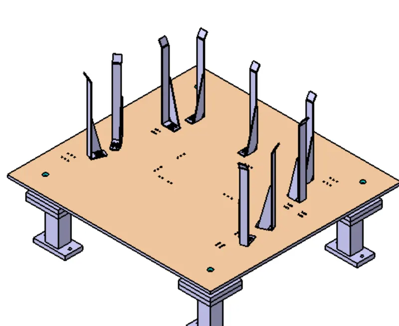
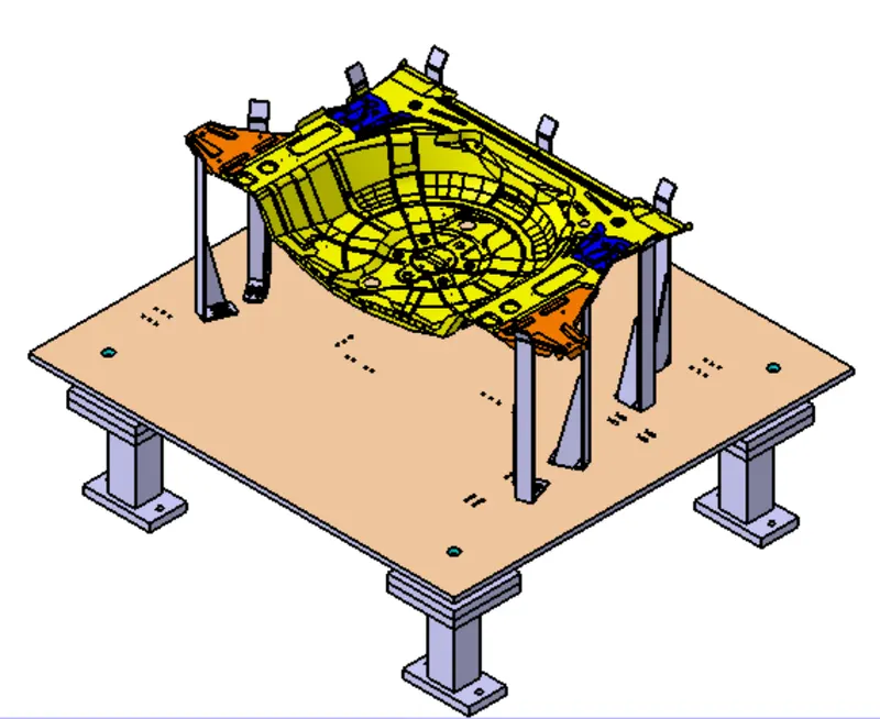
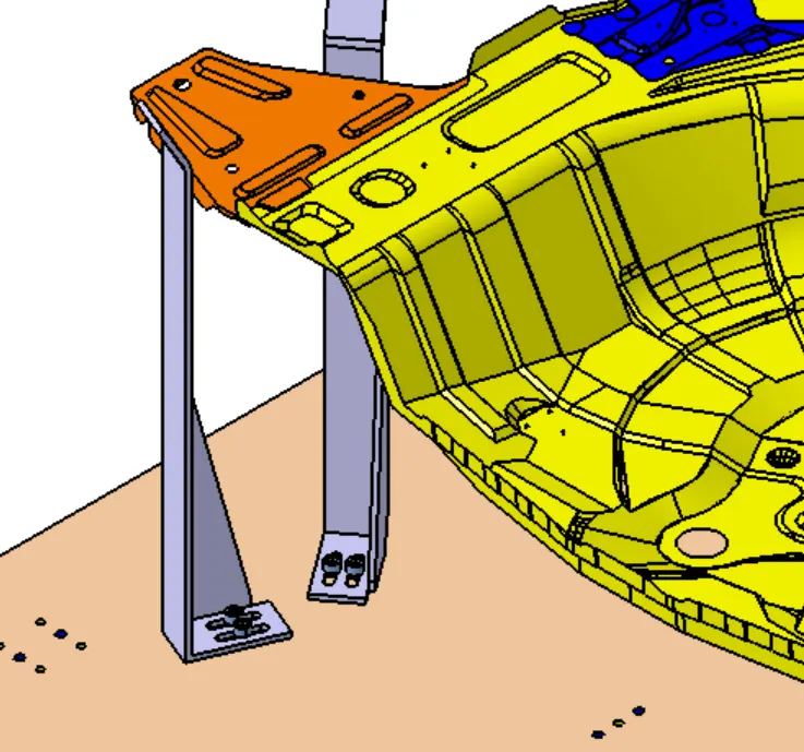
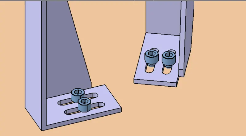
Slots for adjustment
Finishing:
- Design Tree
All the components should be in order and labeling of each part should be as per standards. During structuring of design tree, the workpieces come firs, next comes the base unit, after which pins, rest unit, clamp unit.
All the parts under individual units need to be in order of relation with the workpiece. For example, in pin unit, pin is the key part and comes first after which another part follows.
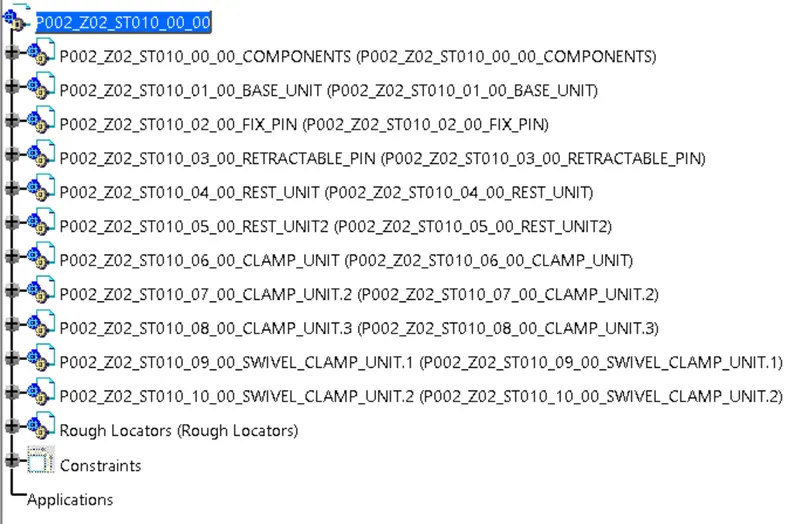
Structuring of all units
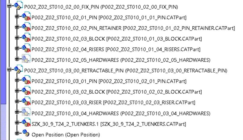
Structuring of pin unit parts
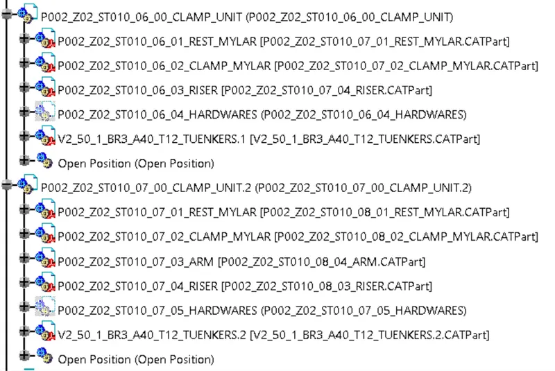
Structuring of clamp unit parts
- Finished Surface
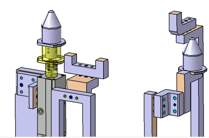
The surfaces that are going to be in contact need to be indicated with skin color for easy identification. These surfaces are machined for accurate engagments of all parts.
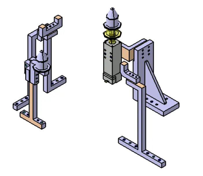
Surface that needs to be machined are indicated with different color.
- Color coding holes
The holes that are threaded, dowel holes and all other holes need to be color coded according to standard used for identification.
Cyan Blue: Open Holes
Yellow: Threaded Holes
Blue: Dowel Holes
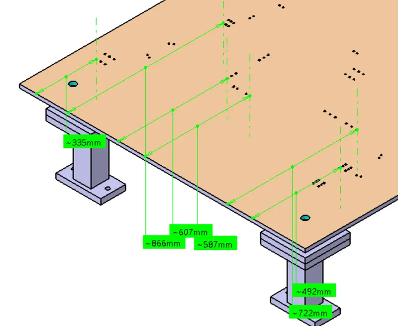
- Nominality of holes on Base plate.
The holes should be round numbers and not in decimals. Therefore it is necessary to position all the holes appropriately.
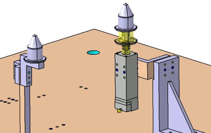
Finishing of various units.
1. Pin Unit
2. Rest Unit:
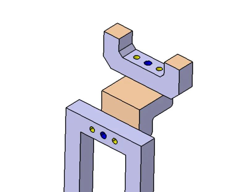
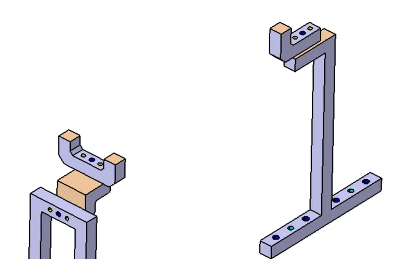
3. Clamp Unit:
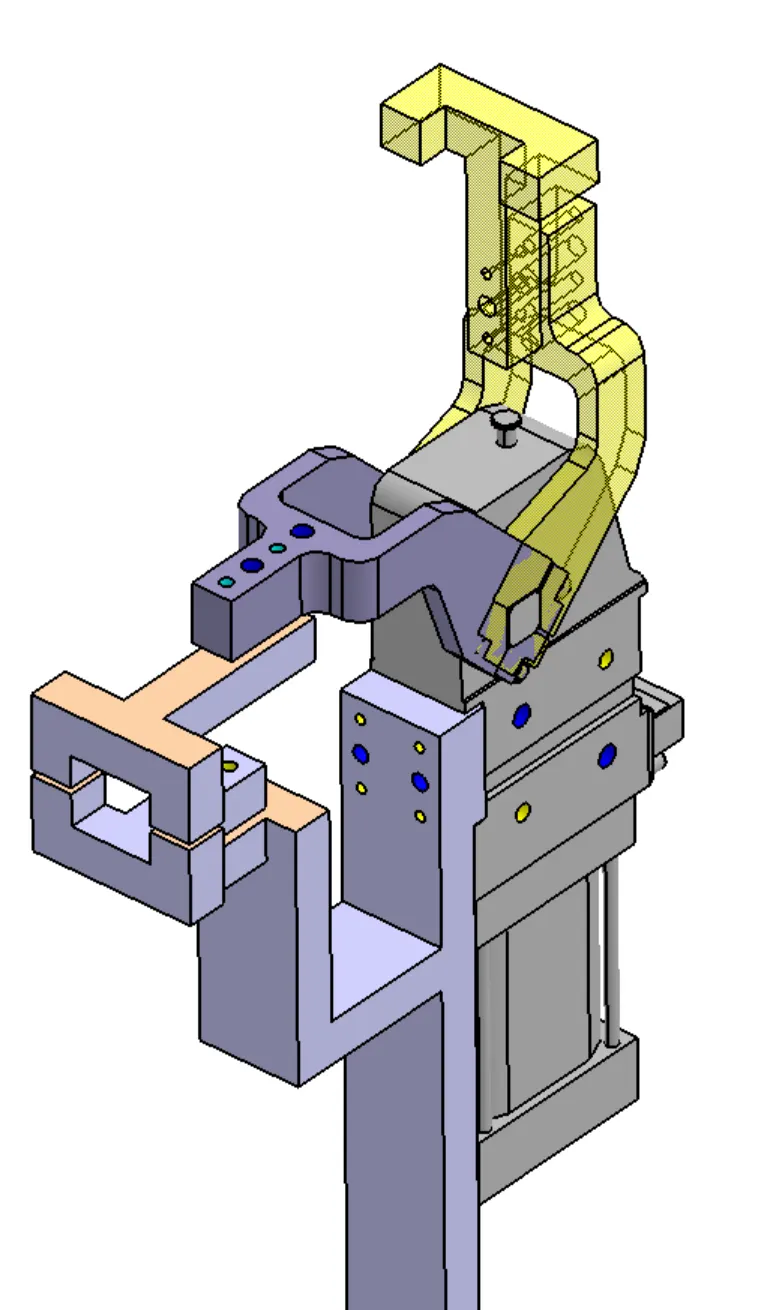
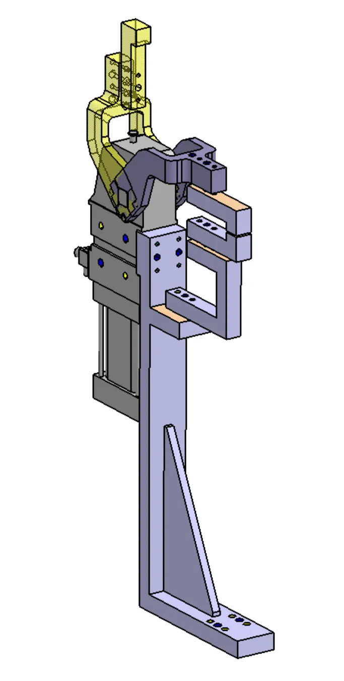
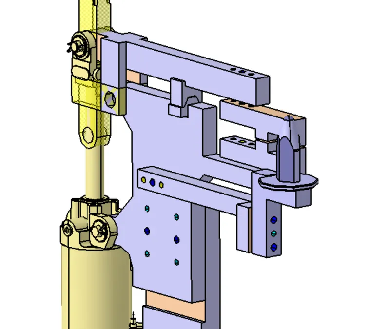
Conclusion: Thus finishing process are carried out on various unit of fixture assembly.