Morphing on CAD model and FE entities.
Aim: - Morphing on CAD model and FE entities.
Morph: - Morphing is an option that helps to modify the CAD or FE without any dimensional constrain. It's the best way to do quick modifications to geometry as well as the FE level. That modification includes adding a new feature, change the position / Direction of features, add rib/ stamp, etc.
It's the time-saving method when comes to instant design change and check.
Normally when a CAD designer did with the design the model send to the FEA engineer for meshing and from there to Simulation. Its long processes with regard to time. If at point of meshing, Engineer points out the modification then instead of stopping the work there and asked the CAD engineer to modify the design as per new arrival conditions it's better to check and modify the design in Mesh level, so on approval, we can go for simulation and if the simulation ends up in success than do the meshing level changes on actual CAD geometry.
Here I did morph on a simple sheet metal component.
In this segment, we will focus on CAD geometry.
After importing the CAD model, I performed the Topo and orient it. After that went for geometry check and clear the possible errors.
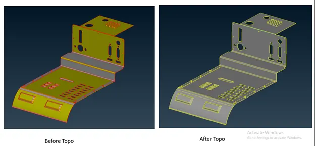
As we discussed earlier, we can perform the Morphing on both CAD models as well as on FE. First, I decide to go with CAD geometry.
Here are some screenshots showing the geometry before and after the Morphing. The areas where I did morph shown by arrows.
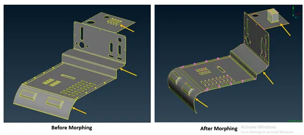
In morphing Deck, you can see the numbers of options like Boxes --> New, Box Morphing --> Move, Direct Morphing --> DFM / Design Change.
Now, Let's discuss the procedure for it.
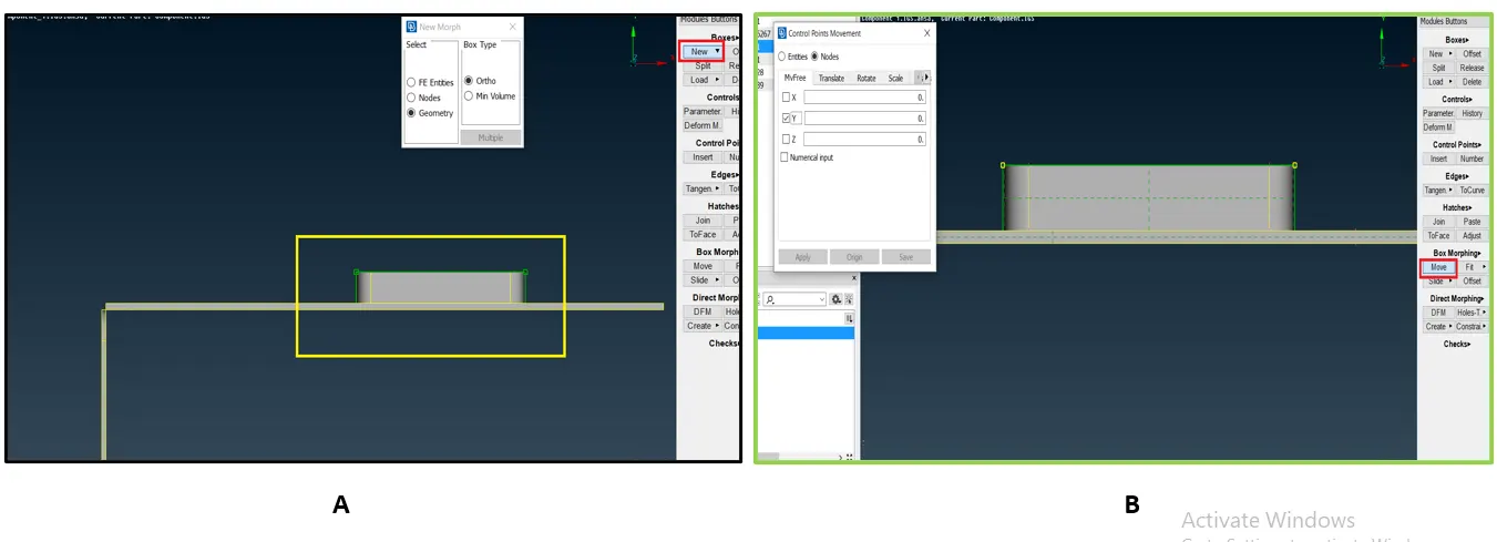
For Morphing the first thing is to activate the morphing Deck.
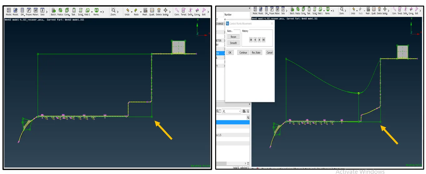
Here I go with box option, in Box option you can find the New option, which will give you the freedom to work on FE entities/ Nodes/ Geometry as you can see in image A.
After clicking on New option, a box will appear that asks you on which sector you want to work wither it is node/ FE/ geometry.
Here I went with Geometry as we are changing geometry using the morph tool in this segment.
After selecting the Geometry option from the pop-up box, I select the geometry on which I want to work, in this case, was a feature that you can see in the above image.
After selecting the geometry, a green color box (cube) appears on the outer periphery of the geometry as you can see in image A.
This box identifies the feature/ geometry on which you want to work. Over that box, nodes get generated that help you to arrange the geometry as you want.
So, to move this not and change the shape of this feature I went to the ‘move’ option in ‘Box Morphing’.
As soon as you click on the move button a box will appear that will give you the freedom to move that points and manage the shape.
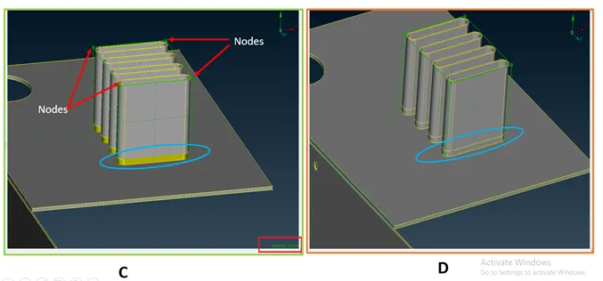
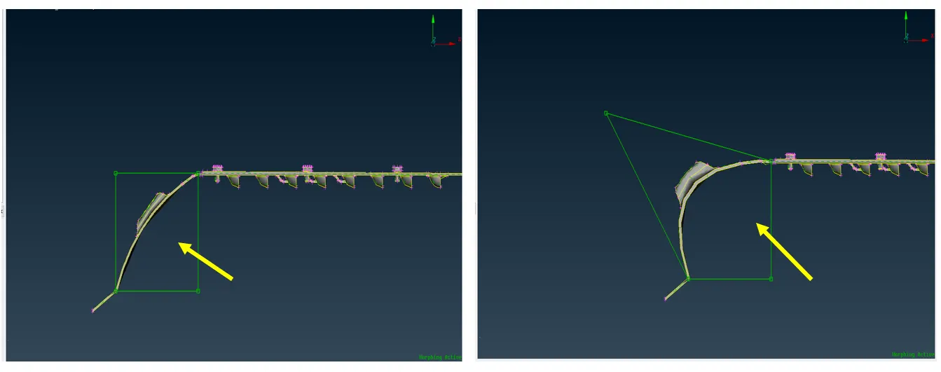
Here are the screenshots of the End results.
As you can see in image C & D, we manage to change the height of the feature.
You can also see the nodes point over the green cube. Also, the activated Morphing window indication over Right Bottom corner.
But. Here is the thing, as per image C the feature we get some geometrical deformation/ defectiveness (indicated by the blue circle)
I overcome this by releasing the connecting double cone and creating a new surface in between.
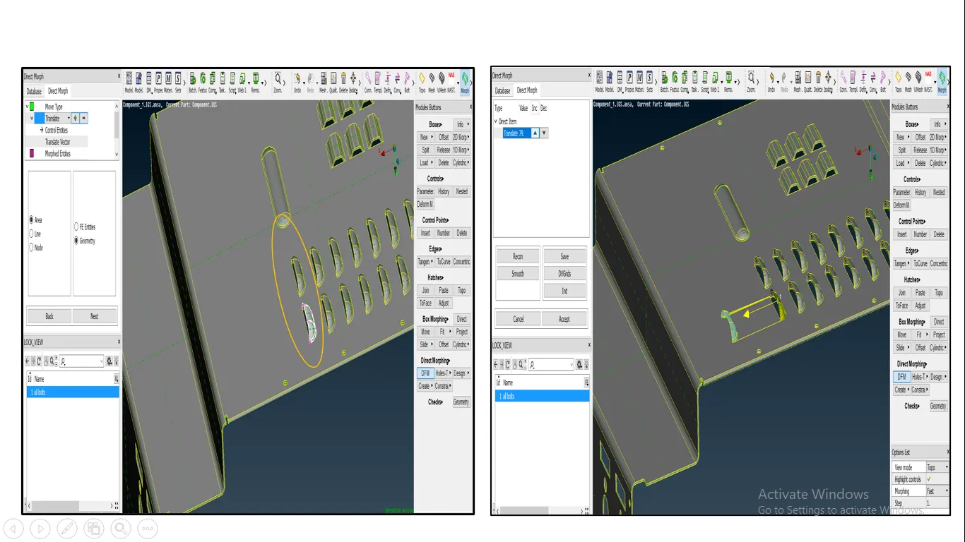
The bottom image is an example of moving the feature, I direct Morphing option you get the DFM option will help you to Translate, rotate, offset, scale, the features.
In this segment, we will focus on FE.
To work on FE first I extract the MID surface, Deployed mesh on it, and then release the Mesh from the geometry.
In this segment, I focus on feature. Performed modifications like copy the feature, change its Scale, rotate it, etc.
In Morph deck inside the Direct Morphing, there is an option for Design change, with which you can move/slide or copy the FE entities.
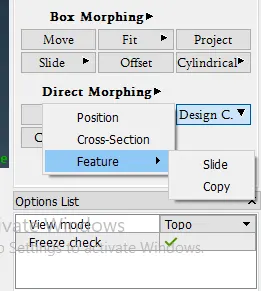
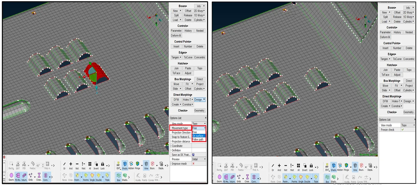
As you can see in the above image I choose the copy option and then copy that feature and placed it nearby, and you can notice one thing here I choose the ‘movement type ‘On the surface from the ‘Options List’ so the feature won’t leave the surface and disturbed the FE.
One more thing here to be noticed is that at the end of command the ANSA will ask you about how much range ‘Reconstruction’ should be done. You can free to choose as 3 element row or more or less than that.
You can see it clearly even after execution of the command there is no disturbance in FE as ANSA is automatically done reconstruction here.
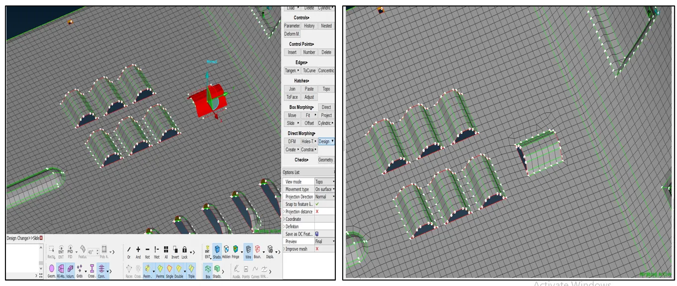
Here I used the Slide option to rotate the feature and you can see the result yourself in the above image.
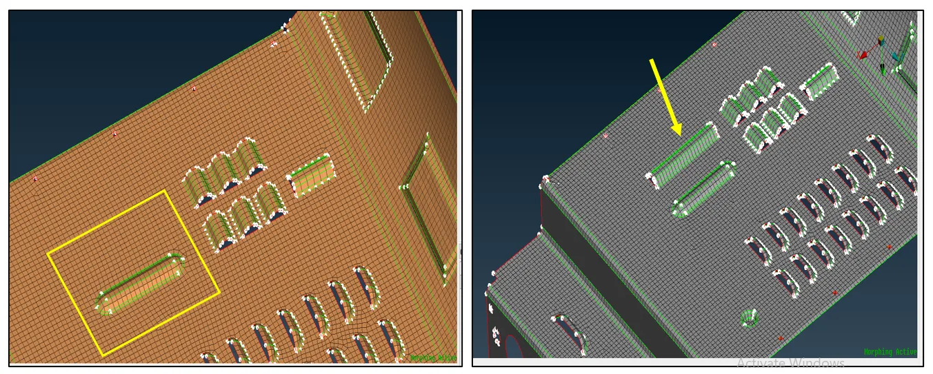
In the above image, you can see the combined use of copy and slide options from the ‘Design Change’ option. Instead of using this, we can also perform the same with the ‘DFM’ option.
Apart from this, we can also add new ribs, bids, stamps, openings on FE using the ‘Create’ option from Direct Morphing.
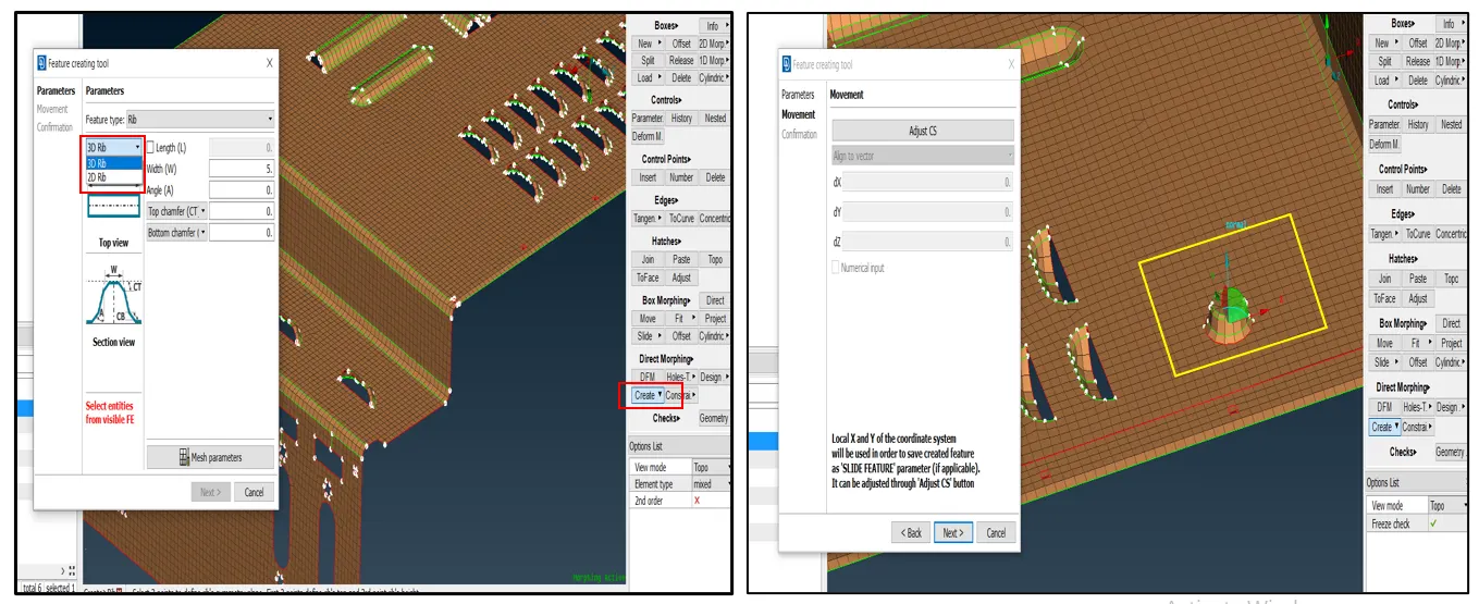
We can create 2D and 3D features with this option. You can see the bead I created in the left side image using these options.
Model Link: - https://drive.google.com/drive/folders/1E5637ycaHrpO_0mJYUMbuSJdaIPJ0eUM?usp=sharing
Conclusion: -
- It’s a better and Time-saving process when it comes to Design modifications.
- Have large numbers of tools to modify the model.
- We can modify the Actual CAD Geometry as well as FE entities, so no matter at which point Engineers needs modification we can pull it out using Morph.
- We can add the strengthening elements like ribs and stamps at the FE level.
- We can to this morph modifications in 2D FE as well as 3D FE also.