Solid Finite Element Meshing over Intake Manifold using ANSA.
Aim: - To check for the geometrical errors and deformation in the newly called model (Tool test). Identify its geometry and perform solid mesh (Tetra) on the component using 3D mesh/ V. mesh deck followed by the given element Quality criteria.
Basic Steps
1) Import model and Go for Length option from mesh module (Deck) to find out the actual geometry of a model
2)perform topo on it. As the model is too distorted after importing from different software. Topo helps to merge the adjacent surfaces and clear most of the errors in the process.
3) After visualizing the model, we get the idea about which category model will fall into. Like sheet metal/plastic/casting part. So, we can choose the meshing option accordingly.
4) For the sheet metal part which has a thickness of less than 6 mm or measurable thickness, we can go with the Shell Mesh option.
5) For casting / plastic part if the part having thickness more than 6 mm, solid meshing is preferred.
6)Check for geometrical errors and clean them.
7) After doing Geometry clean up, now we are ready to do meshing by preferring any of the above methods (Shell mesh / Solid mesh) as per the model given. (Here we are preferring solid mesh as the given tool test model have thickness more than 6 mm)
8) Do Shell meshing by using mesh deck. On the outer surface of the model. Next thing is defined volume and apply the volumetric mesh. For that, we can go for V mesh deck.
8) Do solid meshing (tetra) by using V. mesh deck.
9) Check for any Quality Failure.
Quality Criteria

I am gone do Tetra meshing
- Tetra Meshing: - The tetra elements have 4 nodes as per the below image.
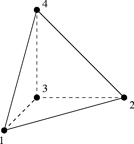
We are using tria mesh here and for better flow pattern ortho tria on the outer surface of the part. So basically, on the surface, we do a normal Shell mesh but using Tria / ortho tria elements only. The basic idea is to create a close volume using shell mesh and then fill that volume using tera elements which are nothing but 3d / solid elements.
For example, take a cube. Square has 6 sides. So, we do shell mesh on each side/surface of the cube and then fill it's inside with tetra elements.
These tetra elements only follow the surface mesh for the first layer of mesh than its just fill the entire volume without following any pattern that’s why it’s also called Unstructured Mesh. The inside tetra element doesn’t follow the surface mesh pattern through the geometry.
Here After importing we get the usual result of distorted faces. As you can see that the geometry is in bad shape. Uneven orientation.
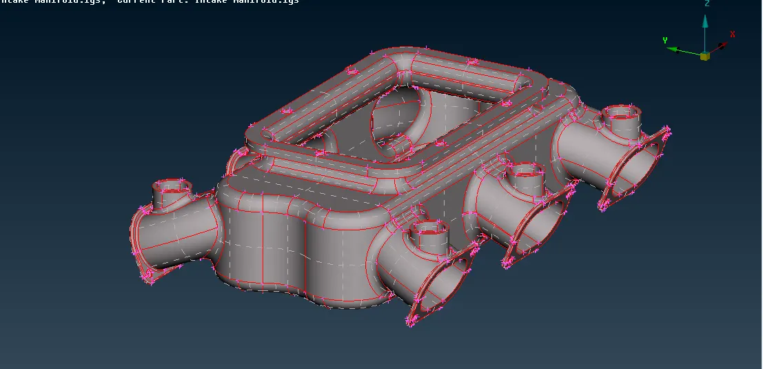
I did topo to clean it also there was no even orientation on the model I just set orientation too. By performing a length option that is in the Mesh deck in the Perimeter block and set it to 0.5mm we can manage the distance between an adjacent node to 0.5mm to get a clearer picture of the model itself.
The next thing I did was performed a Topo operation from the topo Module. What Topo did was it basically connects all adjacent surfaces/ singe cons and completes the geometry.
As you can see in below image After performing the length option and Topo I get the result like this.
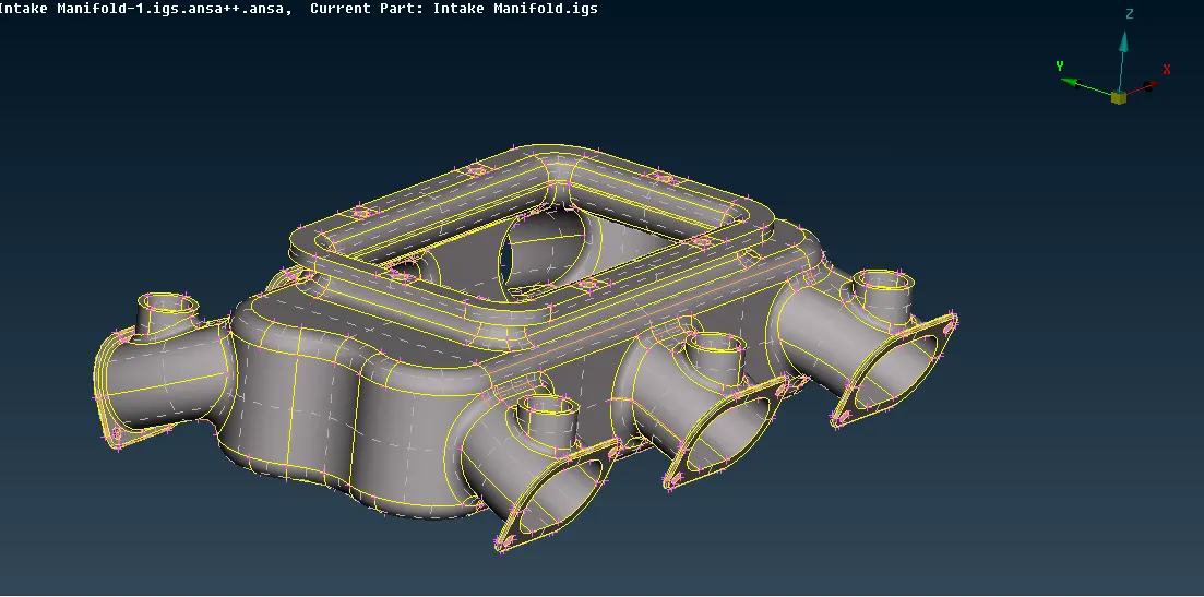
After that, I performed a Geometry check on it. and I didn't find a single error in the model so I moved with meshing.
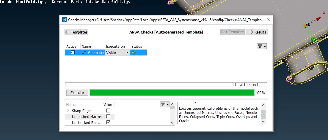
After Geometry cleans up, I have two options one is manually Defeaturing and do meshing, the other method was to use Batch mesh option.
So, I decided to go with the Manual method because it will give me better control over my mesh.
Manual Mesh
Tria :- When the surface was flat plane one.
Ortho tria:- When the surface curved in nature. This will give us better blow and pattern than the only tria option
Here are some screenshots of manual defeaturing.
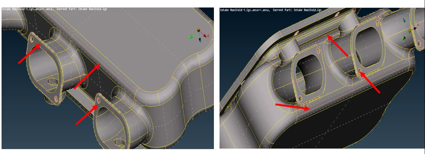
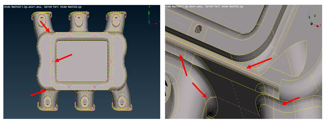
After Defeaturing I moved with meshing and did meshing using options like spot mesh (To generate mesh on blank surface), reconstruct, improve,(improve mesh quality), etc. The final result of shell mesh I get as follows,
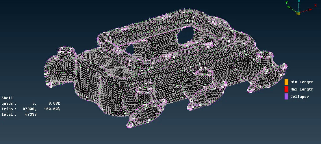
As you can see there are no OFF elements over here.
Errors I find during shell mesh.
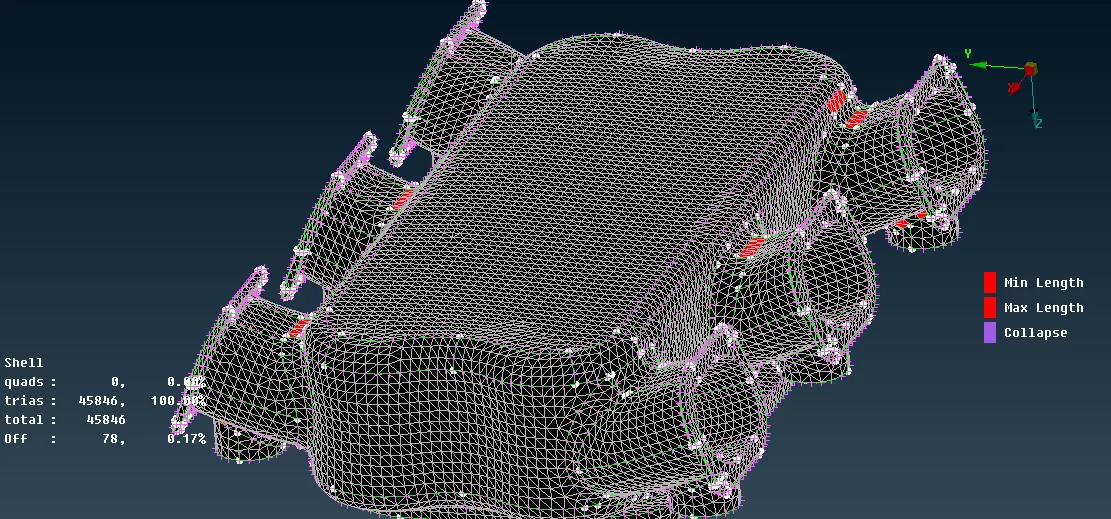
As you can see there were nos. of OFF elements I get rid of them using reconstruct and improve option and that's why our final mesh product doesn't have such off elements in it.
Tetra Meshing
The tetra element generation procedure is the same for both Batch and Manual meshing.
1)First, we have to go to the V. Mesh deck and define the volume for given meshed geometry.
The best way to define geometry it's by Manual method rather than auto one. For that, we just have to long-press "Define" which is in V. mesh deck than it will show two options manual and Auto, Go for a manual one. It will generate the volume and you can check that with the "List" option which is next to the "define". Also, the volume data window will be appearing just below the shell data window [left side one]. As you can see it was showing volume unmeshed: 1. Actually, that means our volume creation is successful and we can move with tetra meshing.
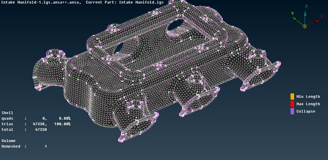
There are two options available for tetra meshing and each of them has their individual algorithms around which they generate the mesh.
- Tetra Rapid
- Tetra FEM
For this model, I went with Tetra Rapid because as per name indicates it did the volume meshing rapidly on the other hand Tetra FEM take exponentially longer time.
With the more complicated model, it may become a reason to the Ansa software crash.
But on the other hand, the mesh quality we getting from the tetra FEM is higher than the Tetra Rapid one. Actually, while volume meshing the Tetra FEM algorithms followed the surface patterns over the at least two layers of mesh but the tetra rapid only followed a single layer after that the entire mesh is unstructured.
So, to save time I went with the tetra rapid option because I thought it will not impact my end result that much.
the final result of the Tetra meshing is as follows,

No Tetcollapse quality failure found out in the model.
Learning Outcomes: -
1) I learned about the 3D mesh. I get a chance to explore more of that volume mesh deck. Importance of 3D mesh (Tetra / Hexa).
2) Understand the right approach while doing meshing on the model which thickness is more than 6 mm / have indistinct shape.
3)Learned new keys in the volume deck like,
Define – which will help to create a new volume.
List – which inherits the list of newly generated volume.
Tetra Rapid / Tetra FEM – to generated Unstructured mesh inside the close volumes.
Then there are Reconstruct to reconstruct the 3d elements and Fix Quality to Auto fixed quality-related issue and many more.
4) Learned that first, we have to use ortho tria on curve part than moved towards the plane part with normal tria mesh
Conclusion
- 3D meshing/volume meshing / Solid meshing only done on the part which has a thickness of more than 6mm.
- Tetra Rapid and Tetra FEM worked on different algorithms which eventually help them to generate the required solid mesh. While volume meshing the Tetra FEM algorithms followed the surface patterns over at least two layers of the mesh but the tetra rapid only followed a single layer after that the entire mesh is unstructured as per the algorithms.
- length and Max. length criteria wouldn’t get applicable to the solid mesh as the elements are 3D elements in nature and we can’t distribute them on basis of 2d perimeters. Though we did check Tet collapse for 3d elements. and it would help to understand the collapse 3d element inside the volume.