Week 7 State of charge estimation
1.Simulate the 3 test cases from harness dashboard and write a detailed report on the results
the steps to simulate and plotting:
1. download the zip file using given link in challenge.
2. extract zip files.
3. in zip files
4. opem matlap and BMS closed loop.
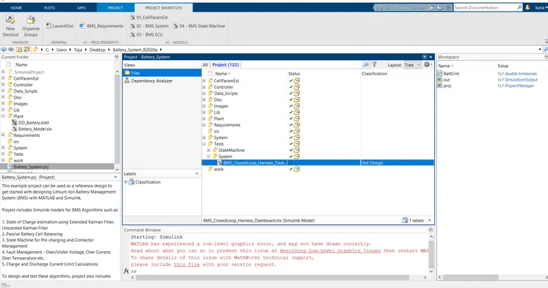
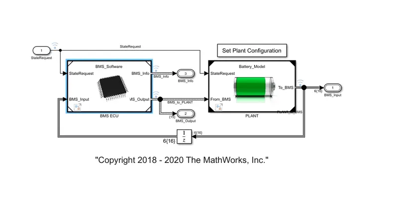
5. now open BMS_ClosedLoop_Harness_Dashboard1, BMS ECU, BMS System as shown below.
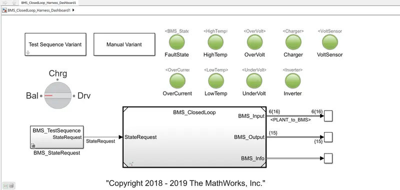
6. now error came while running due to the compiler. so, it is downloaded.
7. test case 1 started running and plotting shown below for it.
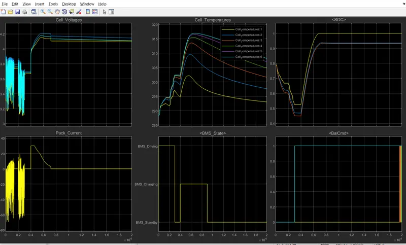
detailed report on the result:
Test_case_1 is running for 20000 secs.
- pack current is the combination of the drive cycle.
- pack current is disharging and charging due to regenerative breaking.
- while the BMS working the cell temperatures are increasing.
- cell 6 has higher temperature because it is in middle.
- and these cells are differ in capacity and cell behaviour.
- to correct these cell network syctem and thermal management system needed.
- after 6000 to 7000 sec temperatures start reducing.
- SOC starts at 80% and went upto 55% we can say it is low at stand by period.
- pack current started charging from 0.4 to 0.9. while charging current is varying.
- initially, constant current charging and then it is constant voltage charging.
- cell voltage increases from 4 to 4.2 while charging after becomes constant voltage.
- constant voltage charging takes more time than constant current.
- while pack current charging, SOC start increasing.
- constant current is from 0.4 to 0.5 and SOC is high at these time and becomes full.
Test_case_2 is running for 20000 secs.
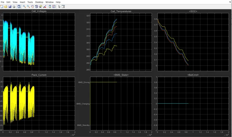
Test_case_2 is running for 20000 secs.
- this test case is in driving state.
- pack current is the combination of the drive cycle.
- pack current is disharging and charging due to regenerative breaking.
- Discharging the pack current increases, while the BMS working the cell temperatures are increasing.
- pack current at 0, voltage is constant at 3.75, 3.65,3.55 approximately and the timings are 0.2,0.4,0.6.
- in this case high fuctuations will see in voltage because of driving state.
- at 0.8 to 0.9 the SOC becomes 0 and the it stops working. cell temperatures are in high state.
Test_case_3 is running for 20000 secs.
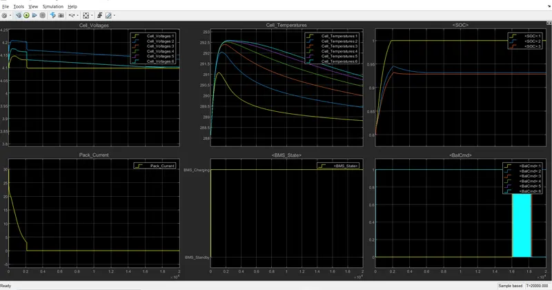
Test_case_3 is running for 20000 secs.
- this test case is in Charging state.
- pack current is the combination of the drive cycle.
- pack current is in charging mode.
- voltage is higher than 4.2 and pack current is decreasing at this condition due to SOC is 100%.
- SOC is at 80% and system starts charging at 0.2 sec SOC is full.
- cell temperatures are high and start reducing after 0.2 sec because SOC is full.
- cell temperatures are low in test case 3(Charging state)compared to test case 1(Fault state) and 2(driving state).
while in driving state the pack current,SOC and voltage fluctuates highly because of charge and discharge takes place simultaneously.
charging is due to regenerative breaking. but in charging state fluctuations are low and also the cell temperatures are also low.
while charging pack current and voltages,SOC are not constant until the SOC becomes 100%.
2.What is coulomb counting? Refer to the above model and explain how BMS implements coulomb counting for SOC estimation ?
The coulomb counting method measures the discharging current of a battery and integrates the discharging current over time in order to estimate SOC. Coulomb counting method is done to estimate the SOC, which is estimated from the discharging current, I batt, and previously estimated SOC values, SOC0.
coulomb counting block will be in closed loop. way to it is BMS_ClosedLoop-BMS ECU (BMS_Software)-SOC_Estimation (SOC_Estimation) as shown below.
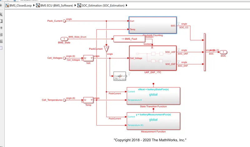
BMS implementatipn for coulomb counting :
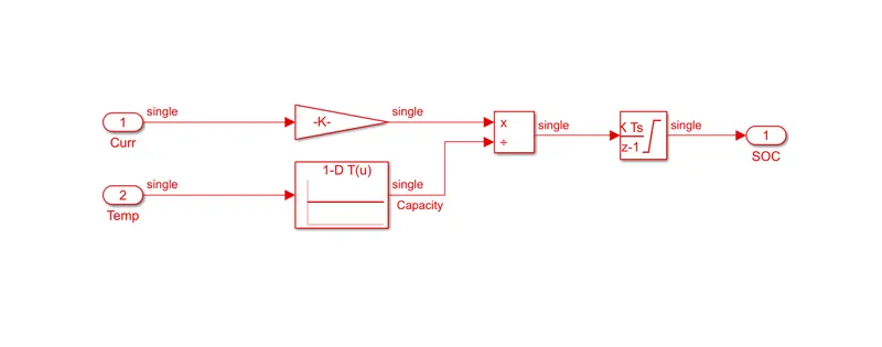
for coloumb counting current and temperature are the inputs.
- temperature will be taken in 1D look up table.
- current will be multiply with gain block 'single(1/3600)'.
- the result will be divided with Temp cominf from 1D look up table.
- coming result will be integrated using the block 'Discrete-Time Integrator'
- now the SOC will be estimated.
it will be done by using the formulae given below.
SOC = 1/C integration(dI/dt)