Week 7 State of charge estimation
AIM:-
1.Simulate the 3 test cases from harness dashboard and write a detailed report on the results
2.What is coulomb counting? Refer to the above model and explain how BMS implements coulomb counting for SOC estimation
What is Battery Management system?
Battery management systems (BMS) are electronic control circuits that monitor and regulate the charging and discharge of batteries. The battery characteristics to be monitored include the detection of battery type, voltages, temperature, capacity, state of charge, power consumption, remaining operating time, charging cycles, and some more characteristics.
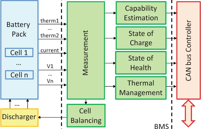
Lithium-ion battery packs are the widely used energy storage systems in electric vehicles. The battery management system (BMS) is responsible for safe operation,
1.Simulate the 3 test cases from harness dashboard and write a detailed report on the results
The steps to simulate and plot the various parameters will be discussed step by step.
By Opening MATLAB-SIMULINK. Click on Open and select the BMS closed loop model. Now we have to open the BMS system and the closed loop harness dashboard. So, we go back to MATLAB window and select the BMS System and open the susbsytem.
The BMS model consists of a BMS ECU (electrical control unit) and a plant. The control unit with its various monitoring and control algorithms is connected to a block with the representation of the battery pack and associated circuitry and peripherals. This model contains two versions of the battery pack: a small one with just 6 cell series, and a larger 16-module pack, each module containing a 6-cell series string. The architecture is 6s-1p and 96s-1p packs, respectively.
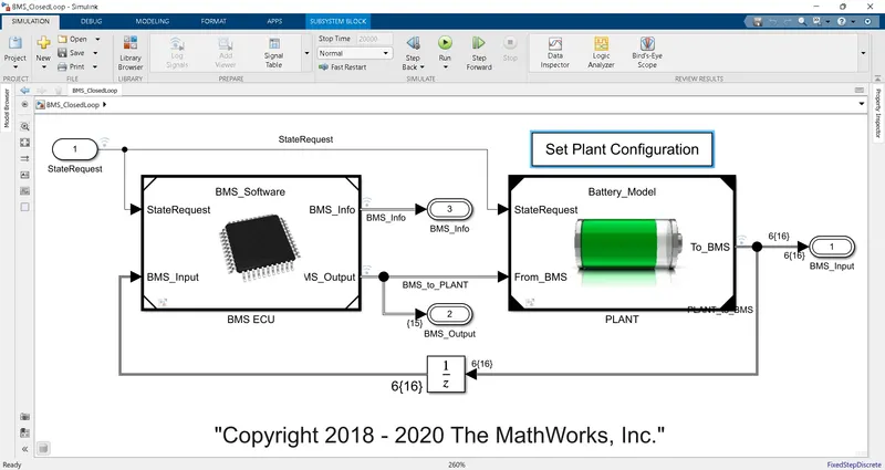
When you click on the BMS ECU, its subsystem opens. Now, click on the state machine.

After opening the BMS system we have to go for the harness dashboard.We have to choose the file where BMS was there and Under the test file, choose BMS harness file.
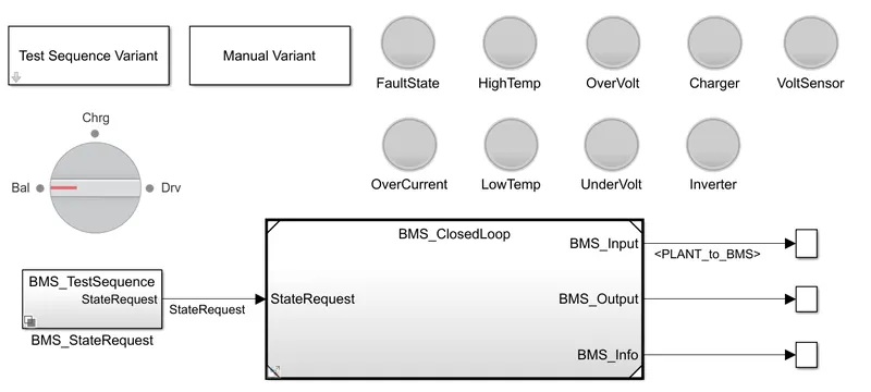
We have to test the three cases by seleceting variant test cases one by one
Test case-1
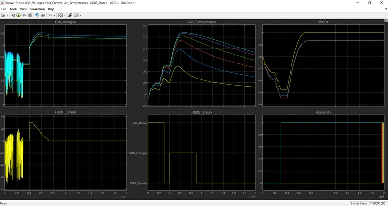
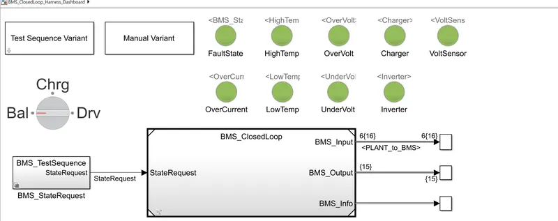
Here, when test case -1 was run, the lamp indication were shown green which means ,there is no fault in the system
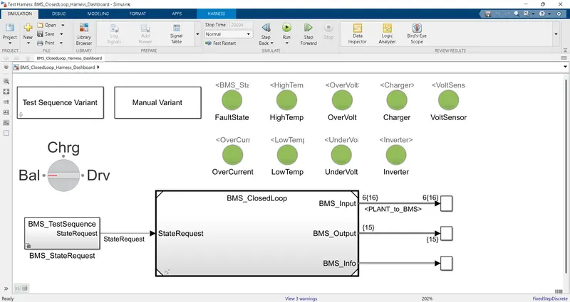
Scope Explanation
Test case-2
Select 2 from the test sequence dialogbox and clck apply
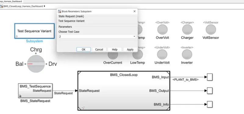
When we run, the lamp indications are green means no fault in the system
Scope results
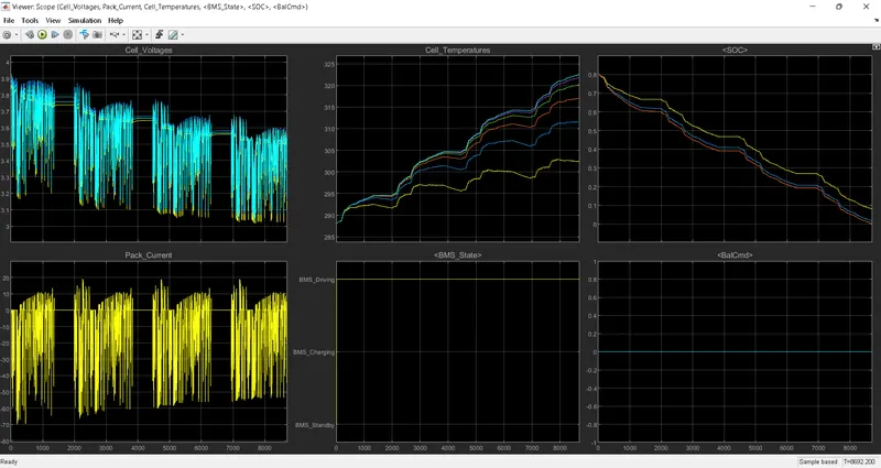
here the plot only driving mode can be performed. The voltage varies from 3.9v max and reduces to 3.5v and cutoff voltage upto 9000sec. Here the SOC reduces from 80% to 0.
Test case-3
select 3 from test sequence dialog box
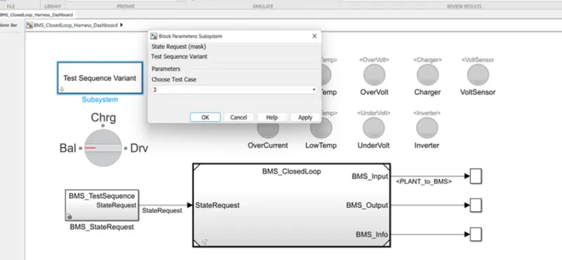
The lamp shows green,here also no fault found
scope
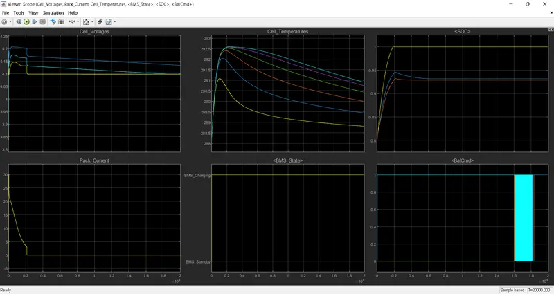
Voltage rises from 3.9v to 4.2v maximum and get stabilised at 4.15v. At 2000sec the pack is fully charged to 100%
Cell-Balancing
Here from 0sec the cell-6 and 2 strats balancing w.r.t. cell-1 and all cells try to balance at end oof the simulation.
Conclusion: Hence all 3 test cases had been run and analysed
2)What is coulomb counting? Refer to the above model and explain how BMS implements coulomb counting for SOC estimation ?
Coloumb counting method:
It is one of the most used methods, However many other factors like temperature, application of battery, life Cycle of battery, fluctuation of battery voltage, etc, need to be considered along with the coulomb counting method to make a more accurate SoC calculation
State of charge SoC:
In simple words (The State of Charge) is your fuel gauge for battery-operated vehicles or E-vehicle. It is the real-time or actual capacity of the battery compared to its full capacity. Just like your cellphone battery, it is measured in terms of percentage (%). E.g.,100% SoC means the battery is fully charged to its capacity, and 0% SoC means it's fully discharged.
Coulomb counting method
Mathematically integrated over the time formula to calculate estimated SOC by coulomb Counting is as below: SoCt=SoCt-1+Ic(t)Qnt
Ic(t) Discharging Current at Time t
SoCt Estimated SoC at Time t
SoCt-1 Previously Estimated SoC at t-1 or SoC value Given by Manufacturer
Qn full battery capacity charges
at Difference in time
It is one of the most used methods, However many other factors like temperature, application of battery, life Cycle of battery, fluctuation of battery voltage, etc, need to be considered along with the coulomb counting method to make a more accurate SoC calculation.
SOC estimated in BMS model
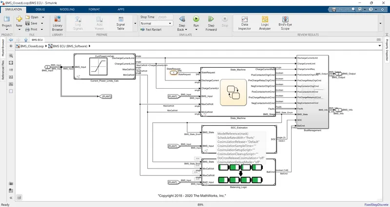
To notice the model of the coloumb counting technique, click the subsystem of SOC and coloumb counting.
it is developed as shown below
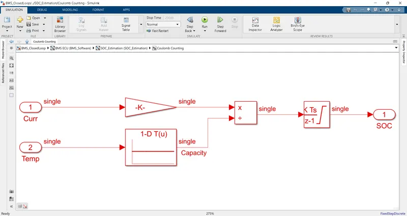
- Here the discharge current from battery given to gain with values as 1/3600 to convert the current to Ahr.
- The values is divided by by capacity due to temp range.then integrated with a gain value of 1 with sample time -1 as we using discrete the integrator.
- The saturation limits are from 0 to
- We will get the SOC values from 0 to 1 multiplied with100 to get in percentage of SoC.
SUBMITTED BY
EV LIVE SESSION BATCH (20)