Week 7 State of charge estimation
BMS,
Battery management systems (BMS) are electronic control circuits that monitor and regulate the charging and discharge of batteries. The battery characteristics to be monitored include the detection of battery type, voltages, temperature, capacity, state of charge, power consumption, remaining operating time, charging cycles, and some more characteristics.
Closed loop simulation of BMS,
Closed-loop control takes the system feedback into consideration for control. Closed-loop control of the motor considers the feedback of motor signals like current and position. The control system uses the feedback signals to regulate the voltage (applied to the motor) to keep the motor response at a reference value.
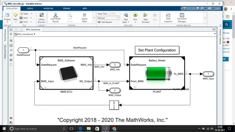
it consist the BMS software and plant configuration both are connected by the state request.
BMS software,
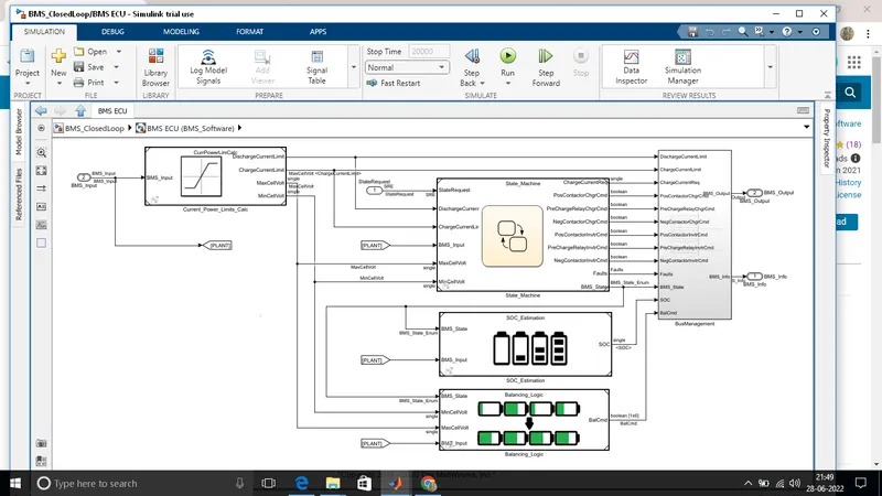
The next step to click the BMS ECU,
the first one define the variable BMS states which indicated standby,driving,chargind and fault.
The second state the switch the fault state is ON in cause current,voltage or temperature reachs unsafe level.
in third & fourth states define conductor ON & OFF switching sequence for charger and invetor.
BY clicking the BMS ECU opening the sub sustem,
The next step isgo back to the simulation,
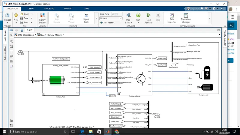
plant battery model,
A battery management system (BMS) maintains the health and safe operation of batteries in a variety of systems such as electric vehicles, aircraft, medical devices, and portable electronics.
BMS closed loop hardness dashboard,
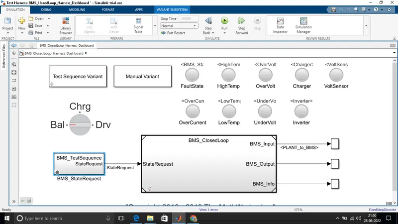
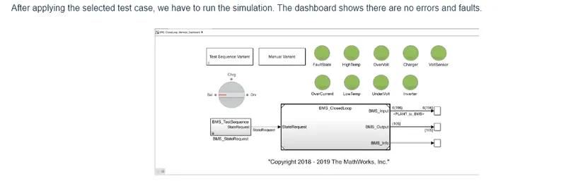
hardness dashboard is shown in below it consist the test sequence varient sub system which having three different test case,this dashboard also help to determine the fault state and other parameter show in figure,if the green colour indicates system working without any error,red colour indicates some error in system running.
charger load,
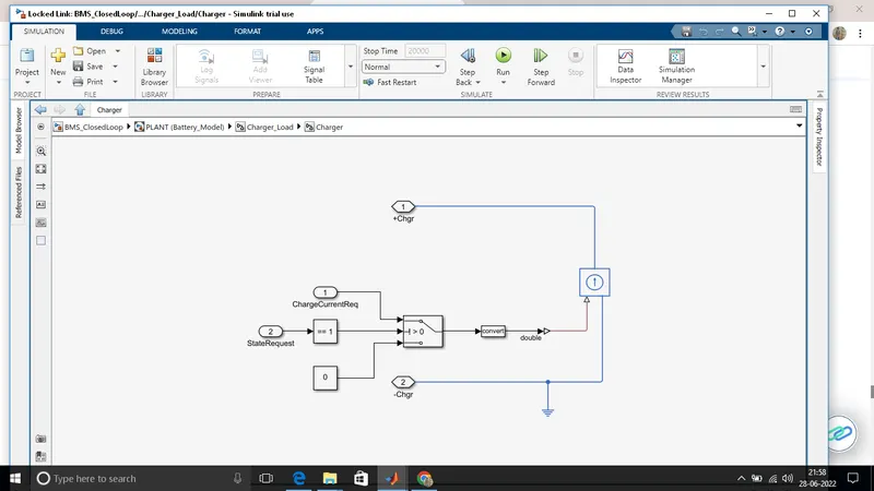
The charge load subsystem are open by plant battery module,
drive load,
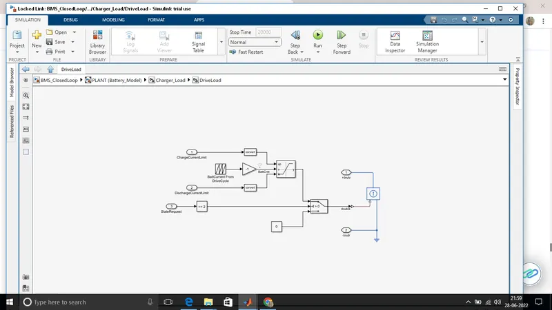
similarly go to load circuit,we can select the library link and open the all libarary link with the load subsystem, the following window open and show the load.
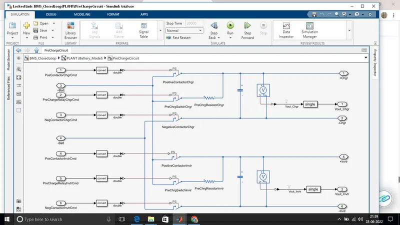
pre charge circut,
By click the plant battery module its open the pre charge circuit subsystem,
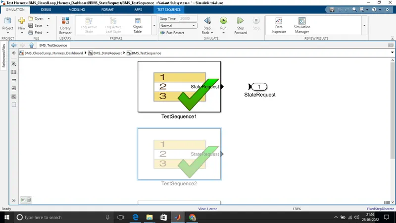
Test sequence,
They having three test sequences,they are test sequences1, test sequences2, test sequences3 each showing different ranges.
they are three state of driving condition,namely
*Driving
*charging
*standby
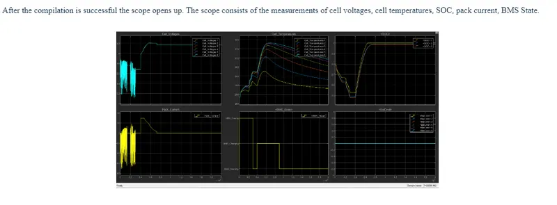
scope result,