Week 7 State of charge estimation
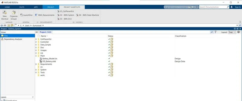
Open the BMS system file from the open option in MATLAB.
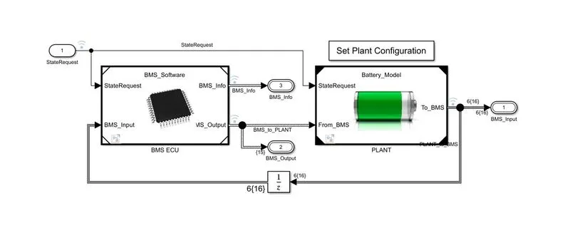
The BMS model contains BMS ECU (electronics control unit) and a plant. The control unit with its various monitoring and control algorithms is connected to a block with the representation of the battery pack and associated circuitry and peripherals. this model contains two versions of the battery pack; a small one with 6 cell series and a larger one with 16 module pack, each module containing a 6 cell series string. The architecture is 6s-1p and 96s-1p packs respectively.
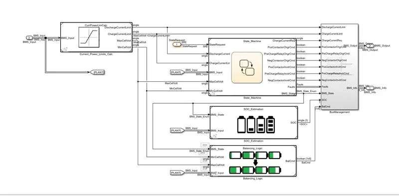
Open the BMS ECU subsystem and open the state machine.
The state machine defines the main operating state of the BMS. The state machine has four parallel state; parallel means those 4 state can be active at the same time:
1. 1st defines the variable BMS_state which indicates-standby,driving,charging,fault. Charging comparises constant voltage stages
2. 2nd switches the fault state ON in case a current , voltage,or temperature value reaches an unsafe level
3. 3rd and 4th states define the contacter ON and OFF switching sequence for the charger and the inverter. This is needed to avoid an excessively large current in rush at the beginning of the charging state. 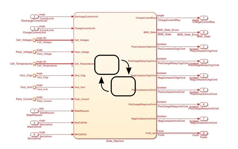
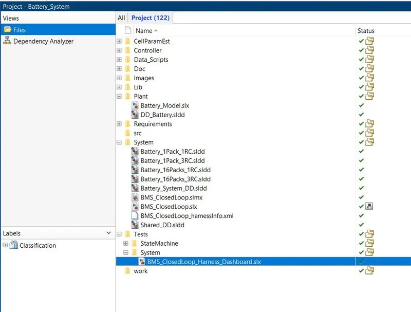
Now after opening the BMS system we have to go to the harness dashboard. this dashboard can be selected from the MATLAB window by the following procedure:
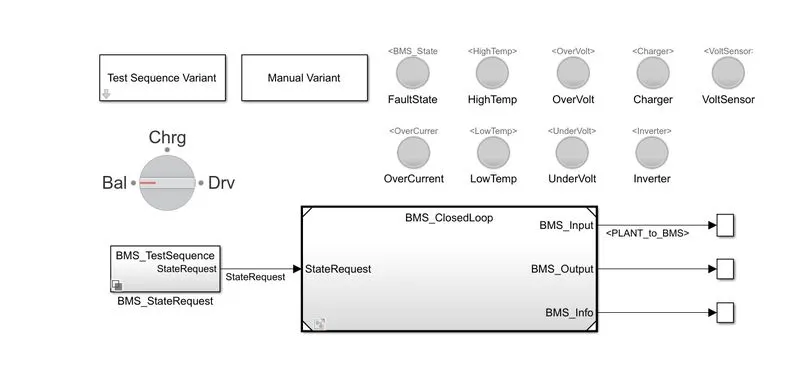
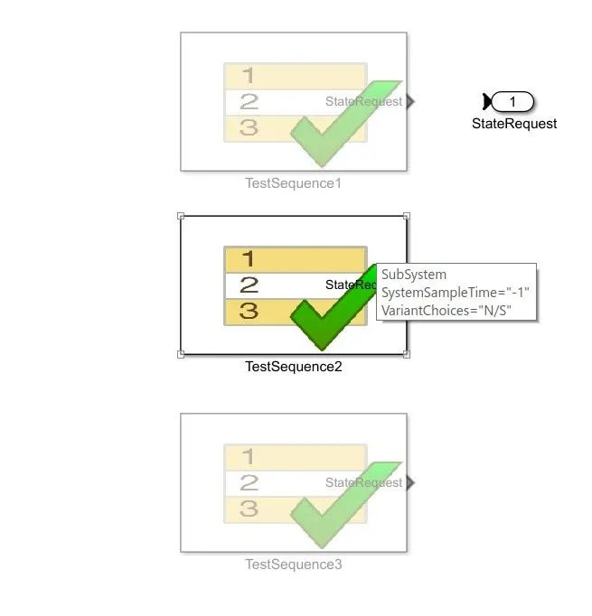
The harness dashboard is shown below. this consists of the test sequence variant subsystem which holds three different test cases. This dashboard also helps in determining the fault states and the other parameters as shown in the diagram below. Green color for the lamp indicates that the system is working perfectly without any errors, while red color indicates there is a fault in the system.
 Test case 1:
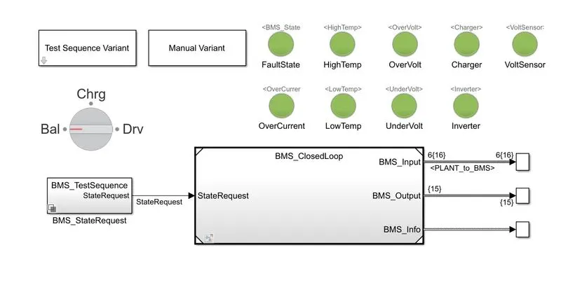
Here in the test sequence variant subsystem the test case is selected as 1.
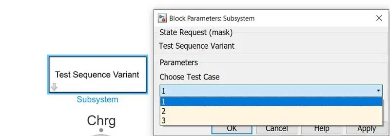
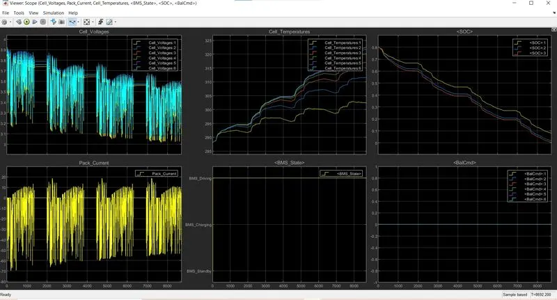
Now compile the model and Run it. After the compilation is successful the scope opens up. The scope consists of the measurement of cell voltages, cell temperature, soc ,pack current ,BMS state.
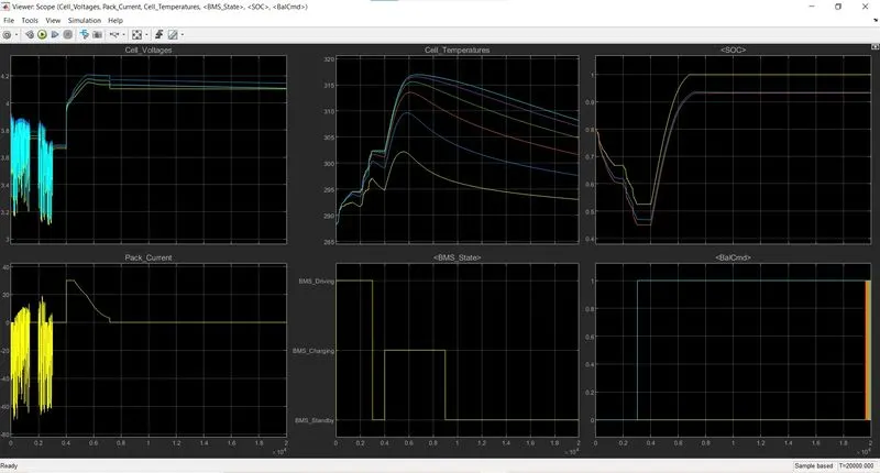
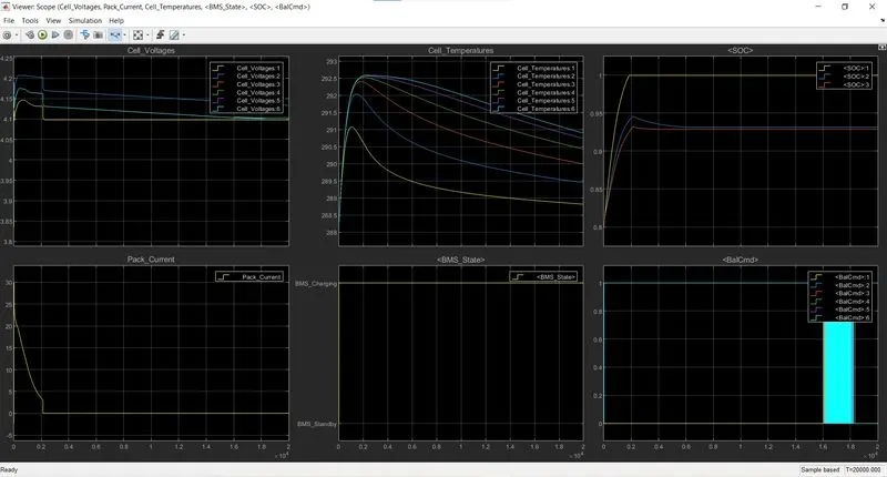
Here we have 6 cells so there is 6 different cell voltages, cell temperatures, and there are 6 balancing command.
And here we can see the 3 different SOC levels.
After running in test case 1 the dashboard shows there are no errors and faults all the lamp will glow green.
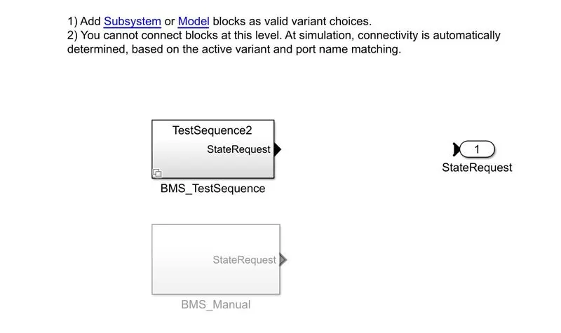
Click on 'BMS'_StateRequest' the following system show. Now click on 'BMSTest _ Sequence'
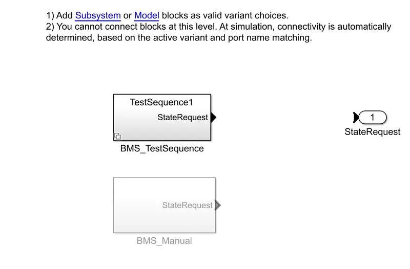
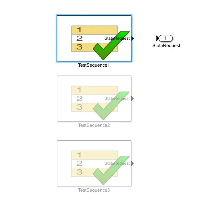
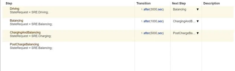
Select the first test sequence and check the conditions for this particular condition;
There are 3 stages of driving conditions:
1. Driving
2. Charging
3. Standby
When the simulation beging, initially the vehicle is in driving state and the SOC will decrease for this time period.After a time period of 3000s the next step is balancing mode and the vehicle is in standby condition.After another 1000s the vehicle is in charging phase and the battery SOC increase almost to 100% . The next phase is the postcharging phase in which the vehicle again goes for standby mode.
From the above scope result we can define that:
1. The input cycle can be seen in the BMS_state plot in which the vehicle initially undergoes driving then charging till SOC=90% and then later in standby state.
2. During charging the battery pack voltage is increased upto 4.2V
3. The cell temperature increases during the driving cycle and then later put into charging untill SOC reaches 100%
4. The current supplied to the EV during the driving phase can be seen in the current plot.
Test case 2:
For this go to test sequence variant and change to test case 2. Then run the model. It shows there is fault. The lamp in the dashboard on the model lights red.
Repeat the same procedures we have done for the test case 1.
This test case has two phases for the battery pack:
1. Driving
2. Charging
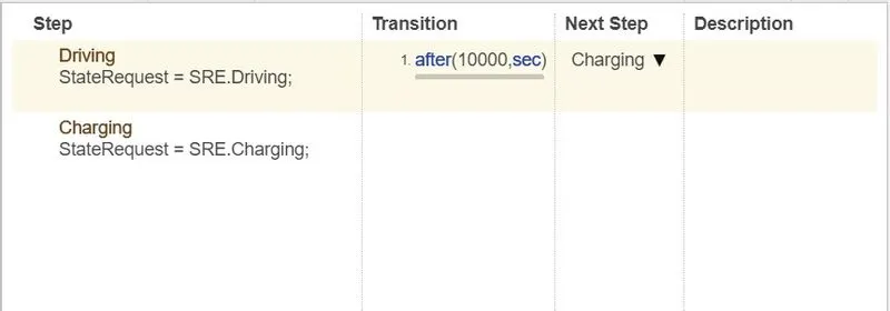
After 10000sec when the driving cycle is over the fault condition occurs and the SOC doesnot increase even for the charging phase.
Test case 3:
After applying the third case, run the simulation. the dashboard shows there are no errors and faults all the lamps glow green.
Click on the 'BMS_StateRequest' the following shows up. Now we have to select the 'BMS_testSequence'
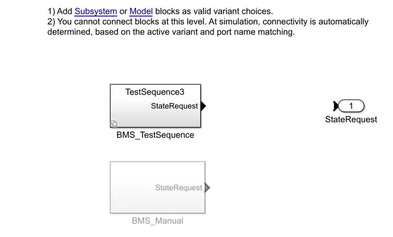
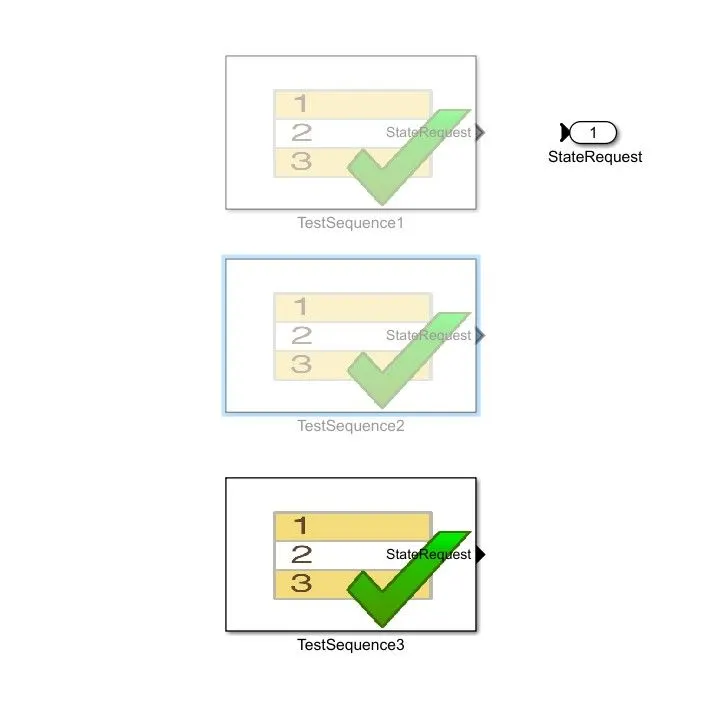
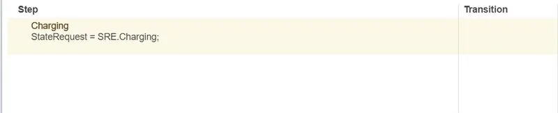
There is only a single phase for the third test case.
1. Charging phase
The scope shows the results for the third test case. Hence the SOC increase from 80% to 100% and then remains in standby mode.
Following these steps we can be implemented to check the faults and errors using the three different test cases from the harness dashboard.
2.What is coulomb counting? Refer to the above model and explain how BMS implements coulomb counting for SOC estimation ?
Coulomb counting :-
The coulomb counting method measures the discharge current of a battery and integrates the discharging current over time in order to estimate SOC. Coulomb counting method is done to estimate the ,which is estimated from the discharging current, and previously estimated SOC values,. SOC is calculated by the following equations:
SOC(t) = SOC(t-1)+I(t)/Qn Δt.
Where,
SOC(t) - battery state-of-charge at time t[%]
SOC(t-1) - battery initial state-of-charge [%]
I - charge/discharge current [A]
t - Time [h]
Cbat - battery capacity [Ah].
But there are several factors that affect the accuracy of coulomb counting method including temperature, battery history, discharge current and cycle life.
First Open the BMS_closedloop model. Then click on BMS ECU.
Now select the SOC _estimation subsystem.
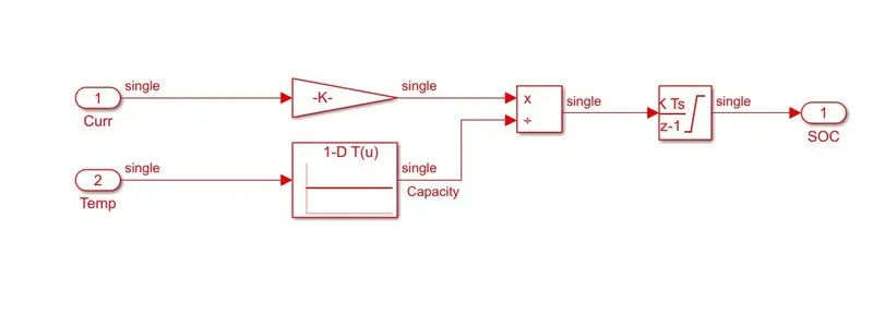
Now open the coulumb counting subsystem;
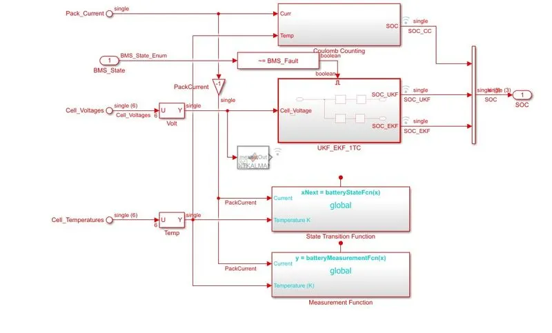
Coulomb counting subsystem:
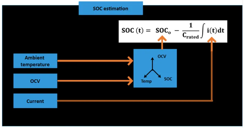
The Coulomb counting method measure the discharging current of a battery and integrates the discharging current over time in order to estimate SOC.
Coulomb counting method is done to estimate the, which is estimated from the discharging current and previously estimated SOC values. SOC is calculated by:
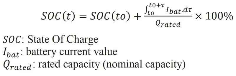
In the above picture for charging the symbol is + and for discharging the symbol is - . The integration is done using the discrete integrator.
The mathematical simulink model for calculation of SOC using coulomb method is shown above.
There are several factors that affect the accuracy of coulomb counting method like temperature, battery history, discharge current, and cycle life.