Week 7 State of charge estimation
1.Simulate the test cases from the harness dashboard and write a detailed report on the results
We need to run simulation for three different cases fro the harness dashboard.
The model was downloaded from the matlab.
The model provides the information of BMS and the faults occuring in the battery pack.
According to the model various faults in BMS are
Fault state
High temperature
over voltage
Under voltage
over current
Inverter
charger
Low temperatureVoltage sensor
The simulink model is
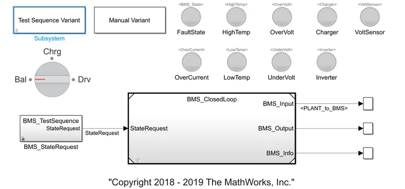
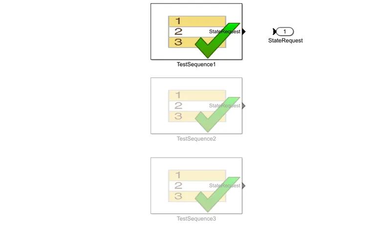
First case, the test sequence variant is set at 1. And the model is run for 20000sec.
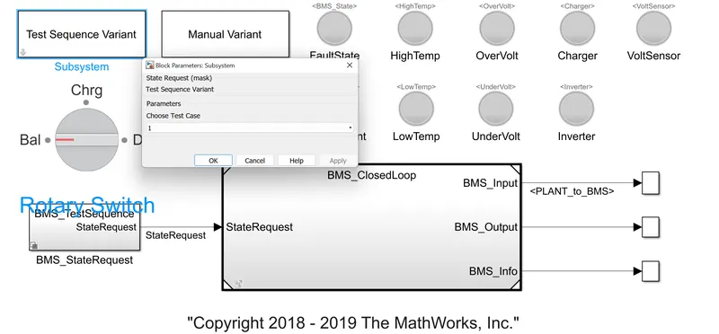
The output is obtained for voltage, temperature, SOC, pack current, BMS and Balancing command
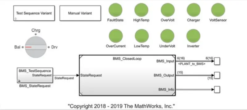
After simulation all the lamps show green light indicating no faults.
The output obtained is
The output graphs obtained
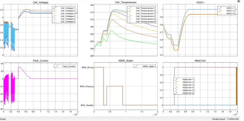
1. The cell voltage and cell current are showing fluctuations in the begining, this is due to the driving action of car. The voltage lies between 3.1V and 4.1V. These stabilizes after certain time.
2.The SOC at this time is decreasing. But when the voltage and current becomes constant the SOC increases.
3.The cell temperature rises during the whole process of driving and charging. Also the cells are having different temperature. This is due to the location of cells.
Second Case
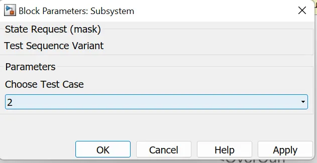
The test sequence is set at 2.
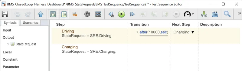
The driving state will be for 10000sec after that charging begins.
Output obtained
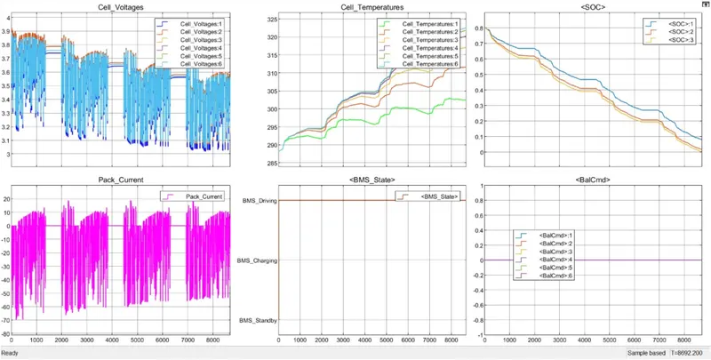
The voltage and current of the cell have been showing fluctuations.
Also at the same time the SOC has dropped to zero.
The current state of the vehicle is driving. The balancing command has reached zero.
The reasons for the same is because of the increase in temperature. The temperature of the cell has shown exponential increase.
This is due to the improper packing of battery pack of electric vehicle.
Third case:
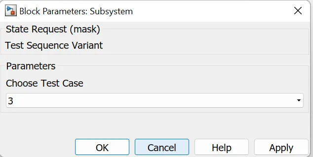
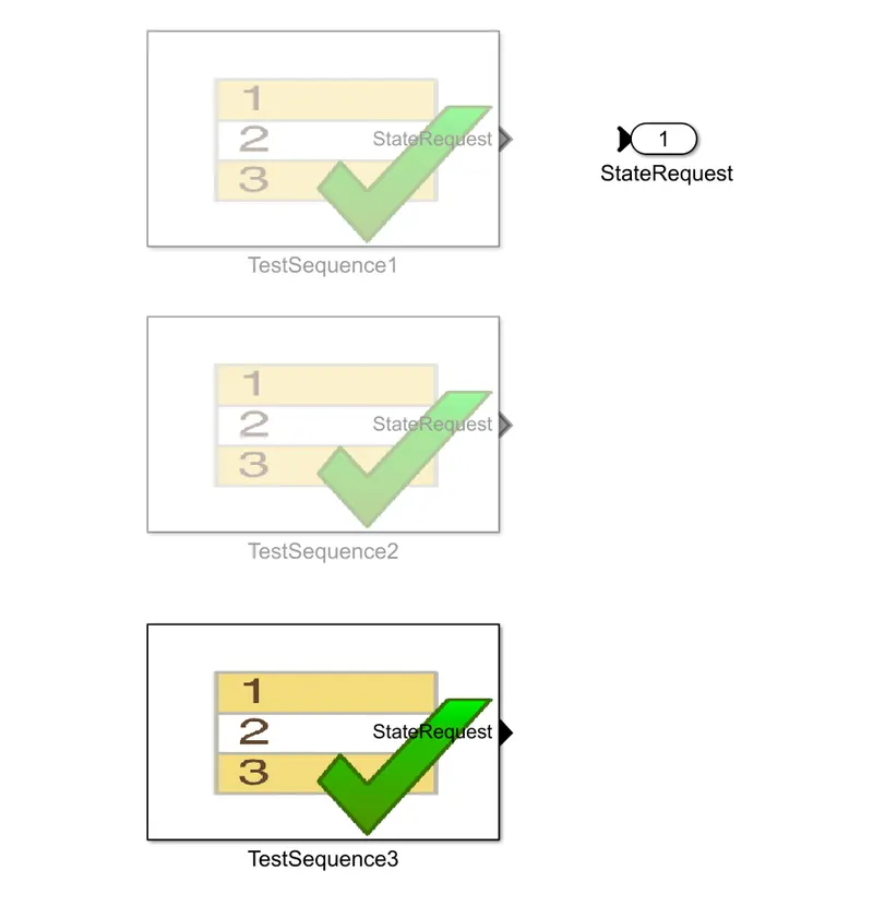
The output obtained is
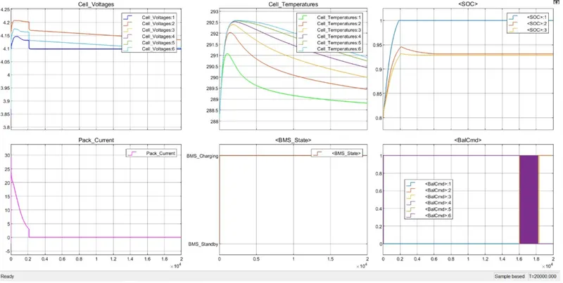
1. The cell voltage has shown an increasing trend in the begining but after certain time the fault happens and the voltage drops between 4.1V and 4.2V.
2. The cell current shows a decreasing trend in the begining. But after 2000sec the fault takes place and the pack current reaches zero value and remains in that position.
3. The SOC steadily increases in the begining and at the time the fault happens the SOC reaches 100%. The battery is in charging condition.
4.The balancing command is high.
5. After the initial increase the temperature drops.
Three cases for the BMS model have be simulated and the results are obtained for various parameters and accordingly the faulty conditons are detected.
https://drive.google.com/file/d/1dyiBWwnygEq9h01T8jBO5xzClk0VXaW7/view?usp=drivesdk
2. Coulomb counting.
State of charge (SOC) is defined as the ratio of the current capacity(Q(t)) to the nominal capacity (Qn).
Nominal capacity is the maximum amount of charge that can be stored in the battery. It will be provided by the manufacturer itself.
SOC(t)=Q(t)/Qn
Different mathematical methods of SOC estimation includes
1. Direct measurement- Uses physical battery properties.
2. Book Keeping estimation - Uses discharging current as the input and integrates the discharginng current over the time to calculate the SOC.
3. Adaptive systems- Self designing and can automatically adjust SOC for different discharging conditions.
4. Hybrid methods.
The Coulomb counting is a method under Book Keeping estimation
Coulomb counting method measure the discharging current of a battery and integrates the discharging current over time in order to estimate SOC.
It is done to estimate SOC(t), which is estimated from discharging current, I(t), and previuosly estimated SOC values, SOC(t-1).
SOC(t)=SOC(t−1)+(I(t)Qn)Δt
But the coulomb counting method has several factors that affects the accuracy which are temperature, battery history, discharge current and cycle life.
Modified Coulomb counting method.
In order to overcome the challenges faced by the Coulomb counting method a new techniwue was developed which is Modified coulomb counting method.
It uses the corrected current to improve the accuracy of the estimation.
The corrected current is the function of discharging current.
Ic(t) =K2(I(t)^2) + K1I(t) + K0
K2,K1 and K0 are constant values obtained from practice expertimental data.
In modified Coulomb counting method SOC is calculated by
SOC(t) = SOC(t-1) + ((Ic(t)/Qn)Δt.
The experimental results shows that the accuracy of the modified coulomb counting method is superior to the conventional coulomb counting method.
The flow chart for SOC estimation is
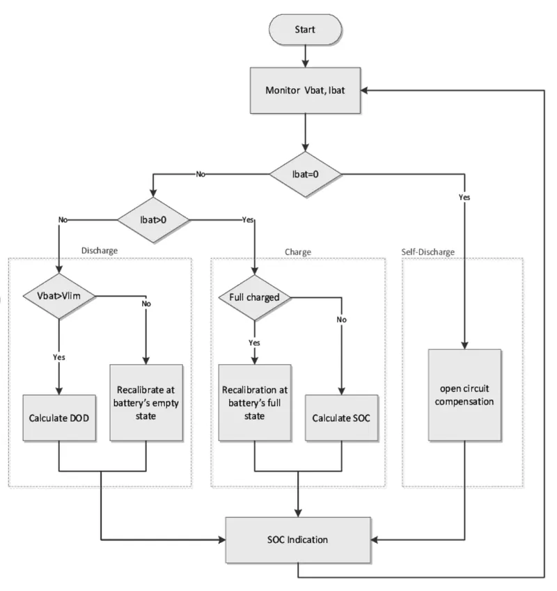
SOC estimation in BMS by coulomb counting method
The coulomb counting method circuit is found in the BMS closed loop block> BMS ECU> SOC Estimation> Coulomb counting
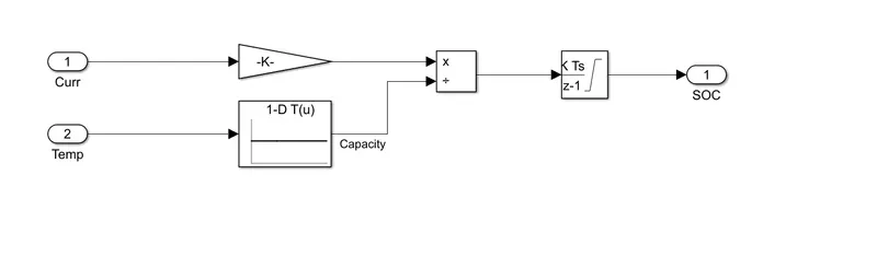
Here the input is Current and temperature.
Blocks like gain, 1-D lookup table, discrete time integrator are used.
The pack current is fed to the gain block having the value of (1/3600) to convert current into Ah.
The temperature is fed into the 1-D lookup table which then provides input to the divide block from the input temperature.
The output is then fed to the discrete time integrator to inegrate the divided current and temperature.
The SOC can be estimated from the output of the discrete time integrator.
Reference:https://www.hindawi.com/journals/isrn/2013/953792/
https://www.researchgate.net/figure/The-flowchart-of-coulomb-counting-method_fig1_305641470