Week - 4
AIM:
To implement control logic ofa washing machine using stateflow in simulink. Also satisfy the following conditions.
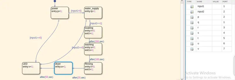
- If the power supply is available, the system gets activated
- If the Water supply is not available, stop the process & indicate through LED
- Soaking time should be 200s followed by Washing time of 100s.
- Then rinsing happens for next 20s & dryer runs for 50s.
Washing machine is an example of control system. In which a process begins immediately after the current process. Wachine machine is used to wash and dry clothes. There are different stages for doing the process.
They are water supply, soaking, washing, rinsing,drying and end.
Here a simulink model have been developed for the simulation of washing machine.
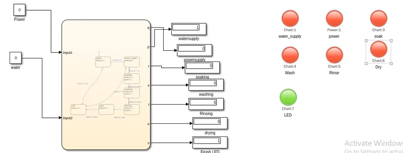
Here when both inputs water and power are zero then no process starts, only LED will light up.
The blocks used for the developement of simulation is constant, display, chart and lamp.
The logic control program is being developed inside the chart satisfying the conditions given. And he variables are assigned in the symbol pane along with port.
The lamps are connected to the output and colour coding has been given to all lamps.
When different time are provided during simulation different stages are turned on
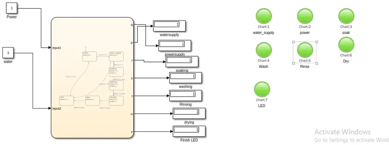
Here the response is obtained when simulation time is given as 380.
The the simulation model has satisfied all conditions and have been successfully executed.
2. AIM:
To develop a simulink chart for the gear shift logic.
The idea is to develop a gear shift logic which changes the gear according to the change in speed.
Speed Range(kmph) Gear
0 to 15 1
16 to 25 2
26 to 40 3
41 to 60 4
Above 61 5
The gear shift mechanism is a manual transmission method in which gear is shift based on the speed range.
Major blocks used for the development of the simulink model are:
1. Slider
2. Constant
3. Chart.
4. Display.
5. Lamp
The model developed is
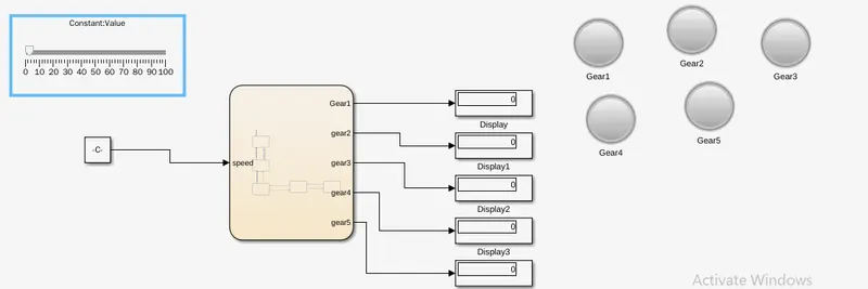
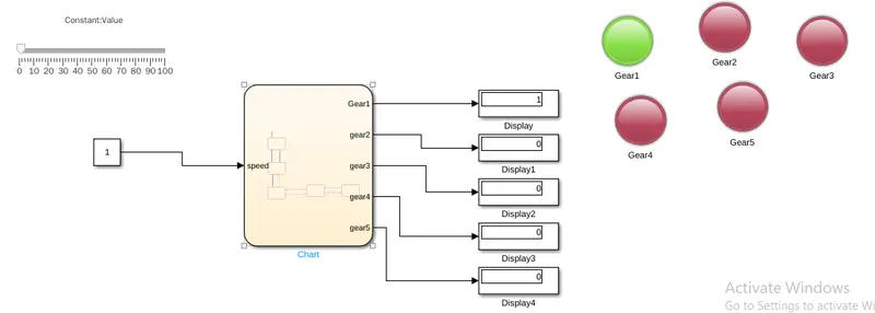
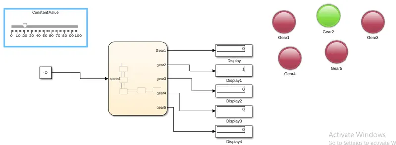
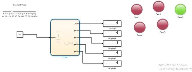
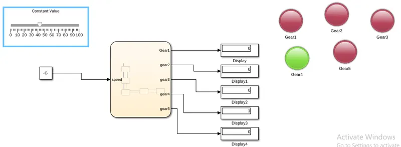
The slider is used as input acceleration. Whenever the slider is varied and simulation is run the gear will shift accordingly.
GEAR 1:
GEAR 2:
GEAR 3:
GEAR 4:
GEAR 5:
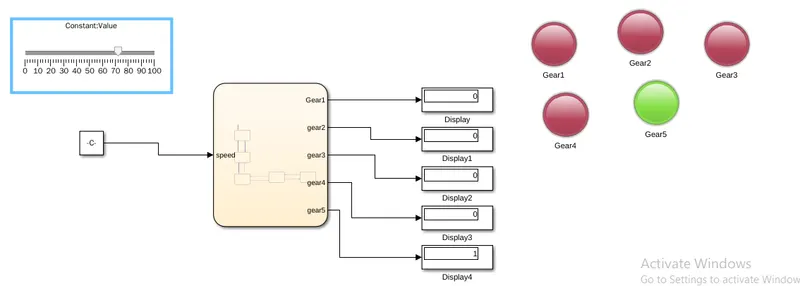
It is clear from the images that gear shifts according to the certain speed range. Here gear shift is represented by lamp. Whenever the gear shift , then according lamp will be turned on.