Week 7 State of charge estimation
Week 7 State of charge estimation
Aim:
1. Simulate the 3 test cases from the harness dashboard and write a detailed report on the results on BMS from Mathworks
2. What is coulomb counting? Refer to the above model and explain how BMS implements coulomb counting for SOC estimation?
Study Case 1: Simulate the 3 test cases from the harness dashboard and write a detailed report on the results
Explanation :
How does selecting the Test Sequence Effect the algorithm:
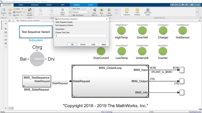
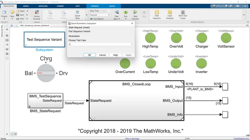
The test sequence can be selected from the harness dashboard
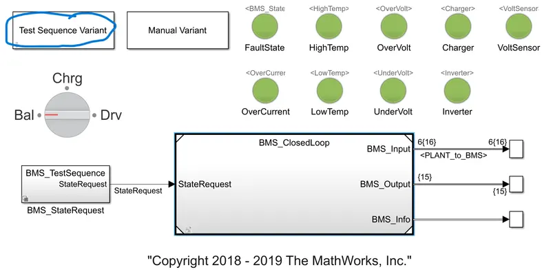
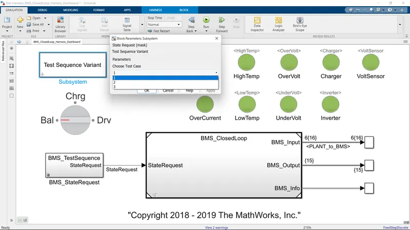
Then a scroll-down menu comes out where we can select the test sequence number.
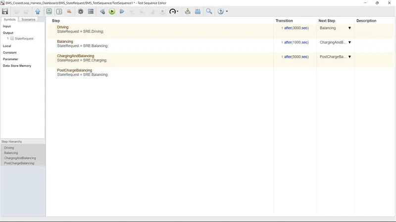
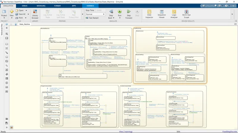
Test sequence 1 has the following states as shown in the image
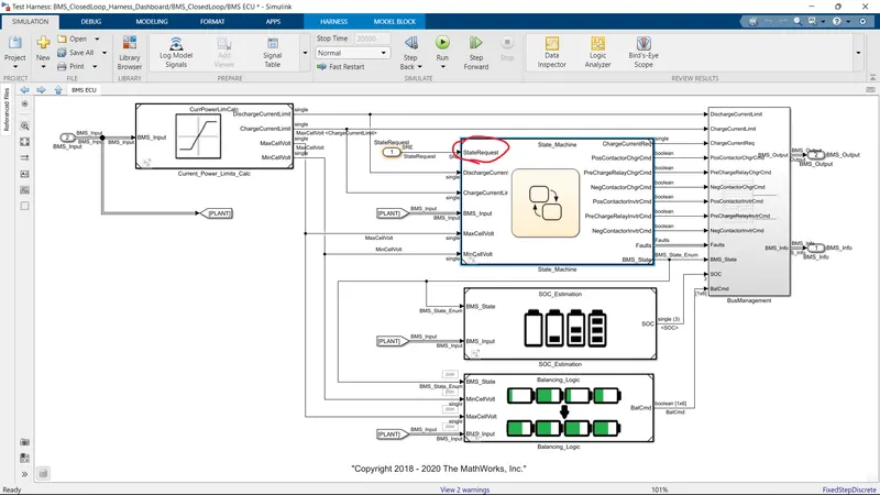
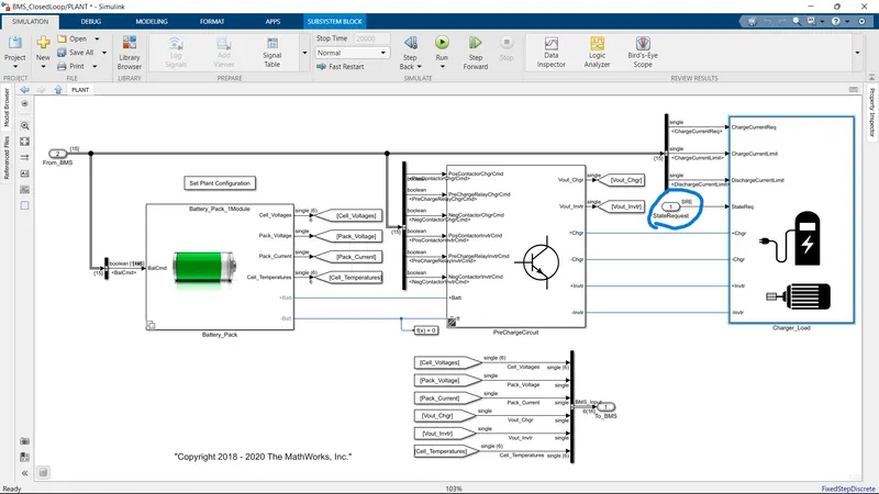
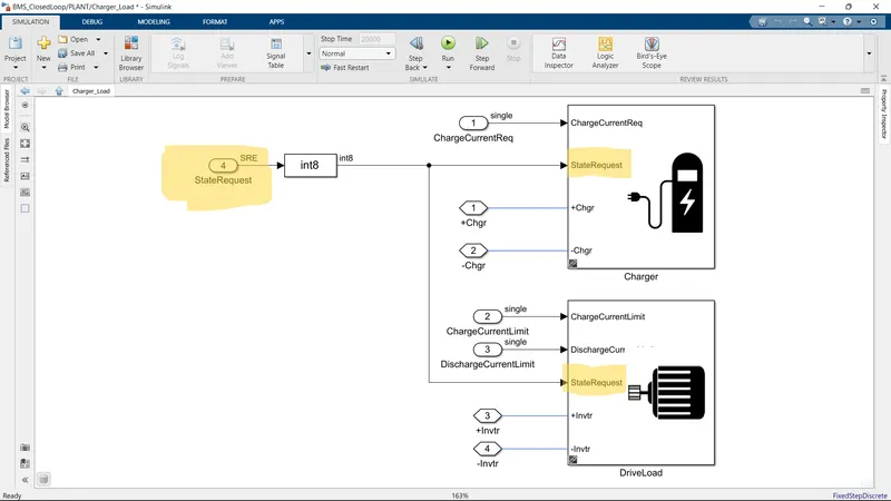
The requested state is given to both BMS ECU and plant model for the following reasons:
1. For the state machine to operate the algorithm
2. For Balancing the cells while charging and Driving
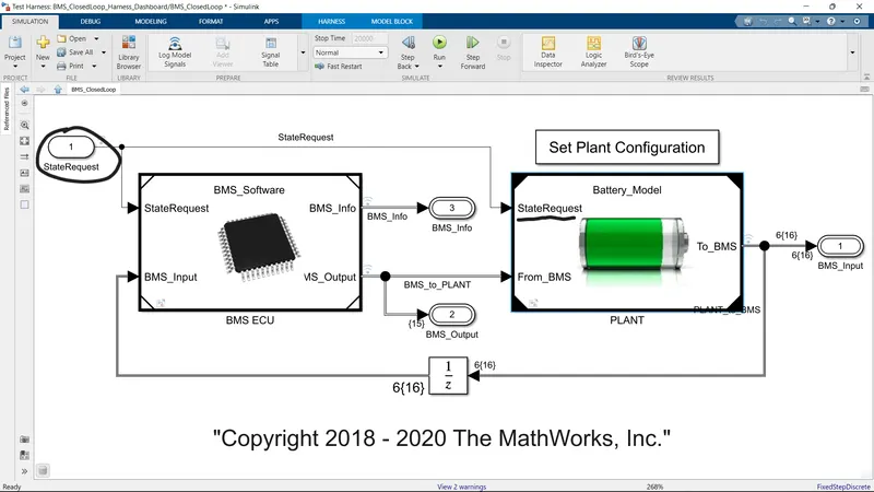
in Battery Model:
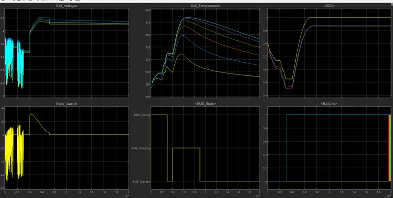
Results of the test sequence 1:
Test Sequence 1 :
Driving State:
1. In the above plot the BMS state shows that the vehicle is in driving condition, Which means there is an energy expenditure from the battery pack for 700 secs of simulation time.
2. Based on the battery current from the drive cycle the voltage source is discharged which can be seen in the Cell voltages graph even the current fluctuations can be noticed and these are completely dependent on the battery current from the drive cycle.
3. The initial SOC (State of Charge) of the battery pack was around 80%, when the drive state has ended the battery SOC estimate decreased to 45% - 47% based on the Kalman filter and extended Kalman filter, But estimation based on Culoumb counting shows 53% SOC the reason for this is discussed in next study case.
4. The Temperature has increased from 287 to 302 kelvins while the vehicle is in drive mode.
5. There is no cell balancing happening during drive command.
Charging State:
1. After the drive mode vehicle is in stand-by mode for 300 simulation seconds.
2. Then the battery pack charging state has started, Here we can observe changes in Voltage, Current, SOC, and Temperature.
3. The Voltage has increased from 3.7 volts per cell to 4.2 volts per cell by the end of the charge state.
4. SOC has reached its maximum level by EOC state.
5. The temperature has raised a lot during the charging state.
Stand-By mode state:
1. Only balancing has changed in its graph, The cell balancing has happened here in this exact phase or state.
2. Voltage, Current, SOC, and Temperature are constant.
Test sequence 2 :
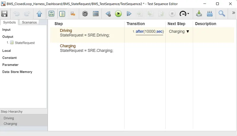
Here we have only two states:
1. Driving
2. Charging
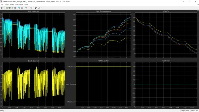
The results from Graphs decoded:
1. There is no cell balancing in this test sequence.
2. State is only confined to drive mode.
3. The SOC of the cell has reached dead bottom hence the simulation has ended.
Test Sequence 3 :
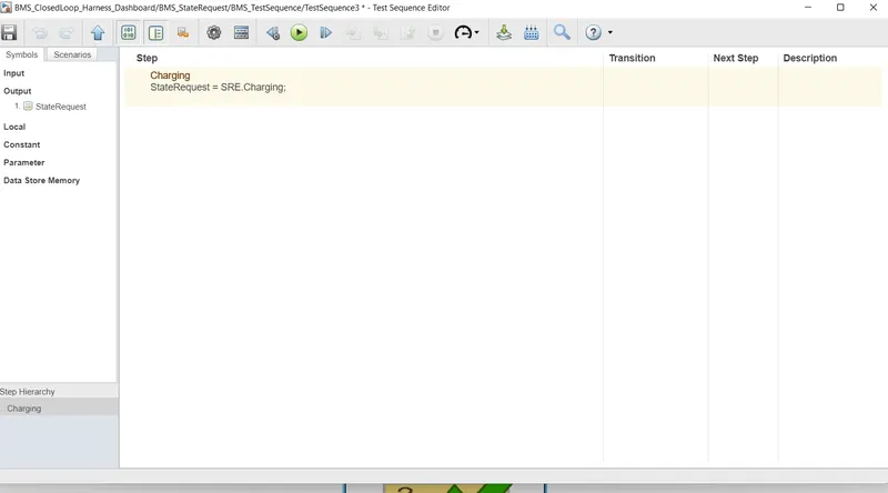
The only state that this test case has is Charging
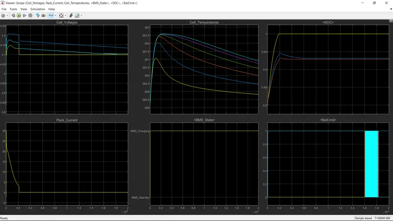
1. Here the charging state has started right from the beginning where the SOC starts from 80% and then goes to 100% according to Culombs counting and 95% by Kalman filter.
2. The cell balancing has started from the beginning itself, the pack current has slowly decreased after a peak charge current.
3. The Voltage has increased rapidly here, and a rise in temp was also observed during this charged period.
Study Case 2:
Coulomb counting is a technique used to track the State Of Charge of a battery pack. It works by integrating the active flowing current (measured in amps) over time to derive the total sum of energy entering or leaving the battery pack. This produces a capacity that is typically measured in Ah.
Below given is the equation of Columb counting in a continuous-time format

Here,
- Z(t) represents the present SOC
- Z(0) represents the initial state of charge
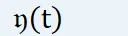 represents Columbic efficiency
- i(t) re[represents the current (present) flowing through the circuit
- Q represents the charge capacity.
But while simulating we don't need a continuous time-based equation rather we need a discreet model, the equation is given below.

The current measurements that are done by the sensor are very much prone to noise, Biasedness of the sensor, and non-linearity of the senor, Hence the true value of current is always prone to error.
- The above is known as coulomb counting, Here error gets added up while integrating hence we need to make a good estimate of initial values
- Self-discharge is not considered here.
- This works only for short period for longer durations the error gets incremented so for every short period we need to reset the values.
- No presence of a Feedback loop.
Modified Columb counting method:
To improve the Coulomb counting method, a new technique called the modified Coulomb counting method is proposed. The modified Coulomb counting method uses the corrected current to improve the accuracy of estimation.
The corrected current is the function of discharging current. There is a quadratic relationship between the corrected current and discharging current of the battery. By the practice of experimental data, the corrected current is calculated by the following form:

where, and are constant values obtained from the practice experimental data.
In the modified Coulomb counting method, SOC is calculated by the following equation:
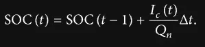
The experimental results show that the accuracy of the modified Coulomb counting method is superior to the conventional Coulomb counting method.
The coulomb counting method implemented in the BMS system in study case 1 :
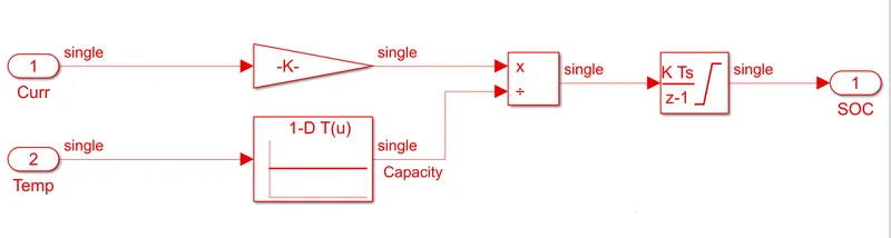
the above model is the implementation of the same equation mentioned earlier, Here in this model, the effects of temperature are also considered.
The problems encountered in Coulumb counting can be overcome using the Kalman filter.
Here we mathematically model the battery pack, and the same input is given to the actual system, and mathematically modeled system the outputs are measured and a feedback loop is given to have less error between the actual system and the mathematical system.
Conclusion: Three test sequences were performed and a detailed report has been made the study case regarding coulomb counting is also completed along with its disadvantages and how the Kalman filter can outperform the coulomb counting method is stated.