Week -2
Aim: 1.Make a Simulink model of Doorbell using solenoid block as per conditions.
2. Use a thermistor to sense the temperature of a heater & turn on or turn off the fan as per conditions.
1.Make a Simulink model of Doorbell using solenoid block as per conditions:
Model:
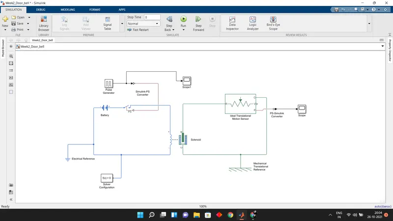
Blocks Used:
1.Pulse generator
2.Switch
3.Battery
4.Solenoid
5.Traslational motion sensor
6.Simulink PS convertor
7.PS simulink convertor
8.Electrical reference
9.Solver Configaration
10.Scope
Modeling Procedure:
Pulse Generator:
1.Here as per conditions Switch need to be in ON condition for 2 Secs and then in OFF condition for 2 secs.
2.We use pulse generator to full the above purpose.
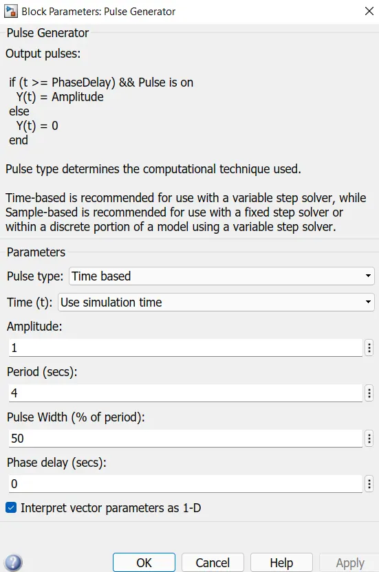
here period implifies total cycle time which is combination of ON and OFF times.
pluse width taken 50% as it is the width of half cycle.
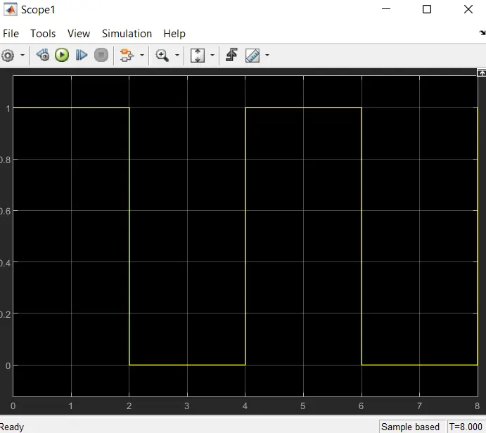
2.Switch needs a physical signal and that is fullfilled by pulse generator,the signal received by switch is shown below
3.Solenoid:
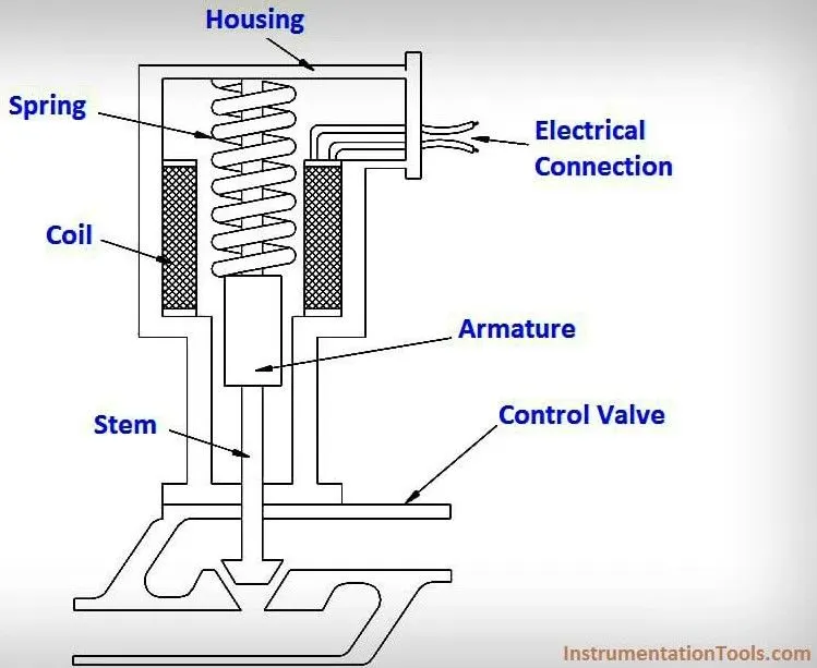
Solenoid works on electro magentic principle,When volatge is supplied across the winding it develops magnetic feild around the coil and causes the movement of Armature ,spring is there to retain armatures position back when voltage is off .
Here switch works accoding to the given pulse signal and that switch controls the volatge accross the circuits which ulimately contorls soleoind.
4.Traslational Motion sensor:
The output port of solenoid is connected to input of Traslational motion sensor,This sensor senses the movement in armature thus we can simulate the signal.
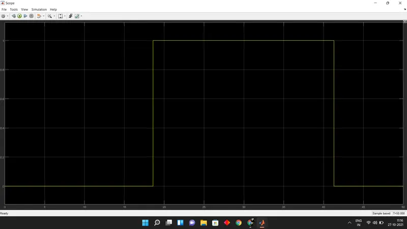
The signal output from the sensor is attached below
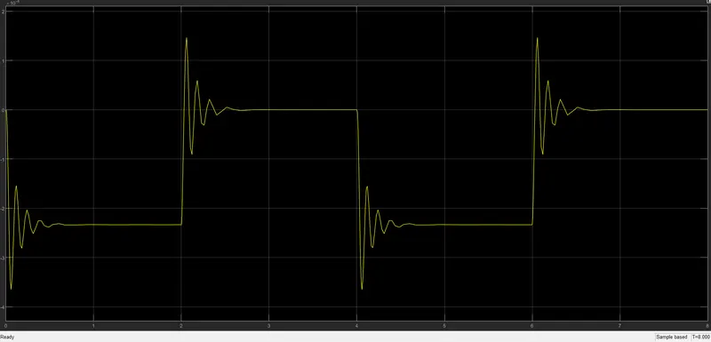
Here the graph shows the positon of solenoid for every two secs.
2. Use a thermistor to sense the temperature of a heater & turn on or turn off the fan as per conditions:
Model:
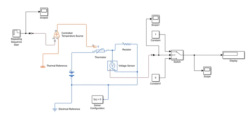
Blocks Used:
1.Controlled Temperature source
2.Thermistor
3.Resistor
4.Volatge sensor
5.Switch
6.Thermal and Electrical reference
7.Scope
Modeling Procedure:
1.Repeating Sequence stair:
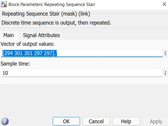
Temperatures are converted into kelvin,Here this singal creator generates signal for 50 secs with mentioned temperatures and the signal can be seen at scope 2,images is attached below.
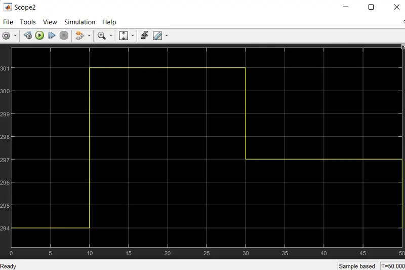
Output of this source is given to Controlled temperature source .
Thermistor:
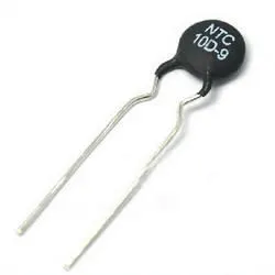
Therm + Resistor = Thermistor
Thermistor is a resistor where its resistance value depends on temperature,hence its called as thermistor.
There are two types of thermistors:
1.NTC thermistors, resistance decreases as temperature rises; usually due to an increase in conduction electrons bumped up by thermal agitation from valency band. An NTC is commonly used as a temperature sensor, or in series with a circuit as an inrush current limiter.
2.PTC thermistors, resistance increases as temperature rises; usually due to increased thermal lattice agitations particularly those of impurities and imperfections. PTC thermistors are commonly installed in series with a circuit, and used to protect against overcurrent conditions, as resettable fuses.
Resistor:
The resistor is a passive electrical component that creates resistance in the flow of electric current. In almost all electrical networks and electronic circuits they can be found. The resistance is measured in ohms (Ω). An ohm is the resistance that occurs when a current of one ampere (A) passes through a resistor with a one volt (V) drop across its terminals. The current is proportional to the voltage across the terminal ends
Volate sensor : senses fluctuations in volatge
Switch Case: a Constant value 1 represents switch is in ON state and constant value 0 represents OFF state,The conditional statement is passed through input port.
When ever the temperature is higher than 27 Deg centigrade the switch is on in state,which means power flows through the circuit to fan.
After the switch case we use scope block to visualise the switch working,and the graph is attached below.