State of charge estimation With Simulation of BMS
1.Simulate the 3 test cases from harness dashboard and write a detailed report on the results
2.What is coulomb counting? Refer to the above model and explain how BMS implements coulomb counting for SOC estimation ?
Question 1.
Simulate the 3 test cases from harness dashboard and write a detailed report on the results
Answer 1.
Simulation of BMS or BMS in Closed loop simulation
- Here, I had used this link for BMS ClosedLoop
- From this Simulink model we get idea about Battery Management System (BMS) Cell voltage, Cell temperature, Peak current, State of change (SOC) and so on.
- There are various types of defects occurring in this system which is in below.
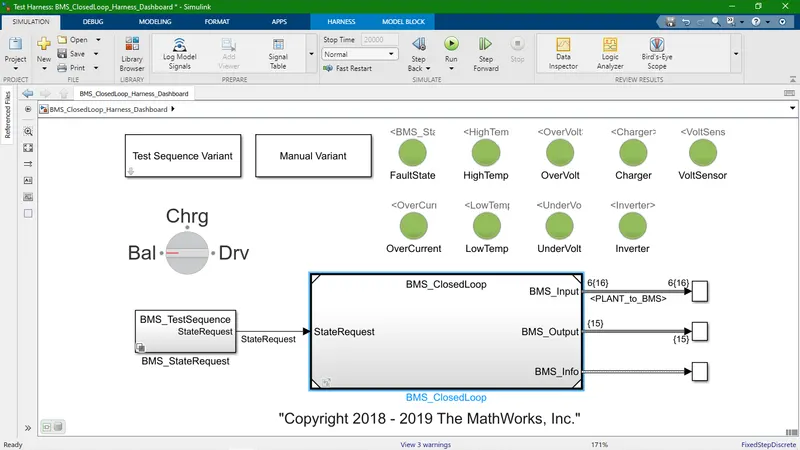
- If there is an any fault found in system at that time red color lamp is bright otherwise wise green.
- Fault state
- Over current
- High temperature
- Low temperature
- Over volatge
- Under voltage
- Charger
- Inverter
- Volt sensor
- This is a BMS_ClosedLoop harness dashboard.
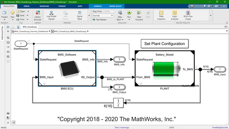
- Here, This is BMS_ClosedLoop system main part BMS ECU and Plant.
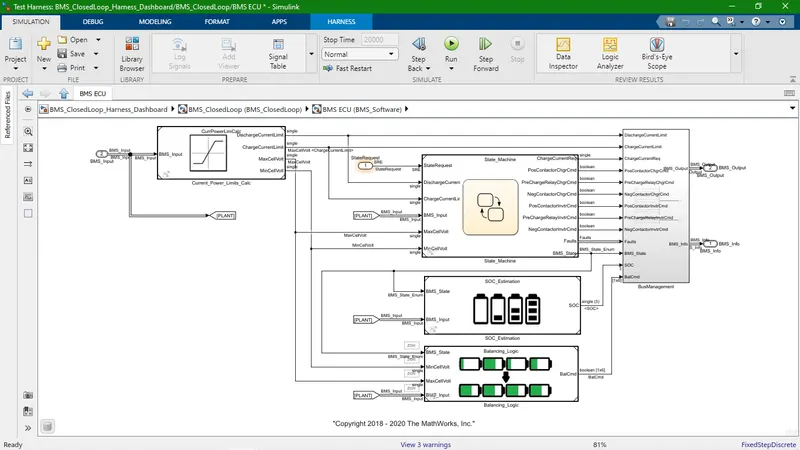
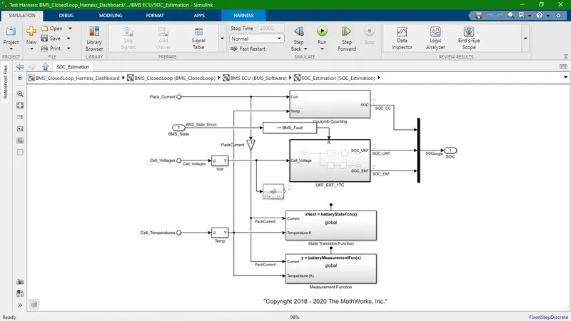
- Inside of BMS ECU, there is state machine, SOC Estimation, Balancing Logic blocks over here.
- This is inside of Plant, there are Battery Pack, Pre-Charge Circuit, Charger, Drive Load blocks available.
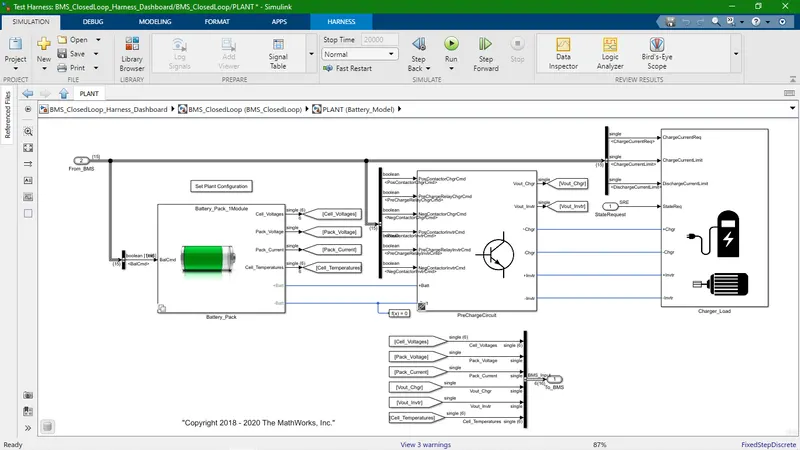
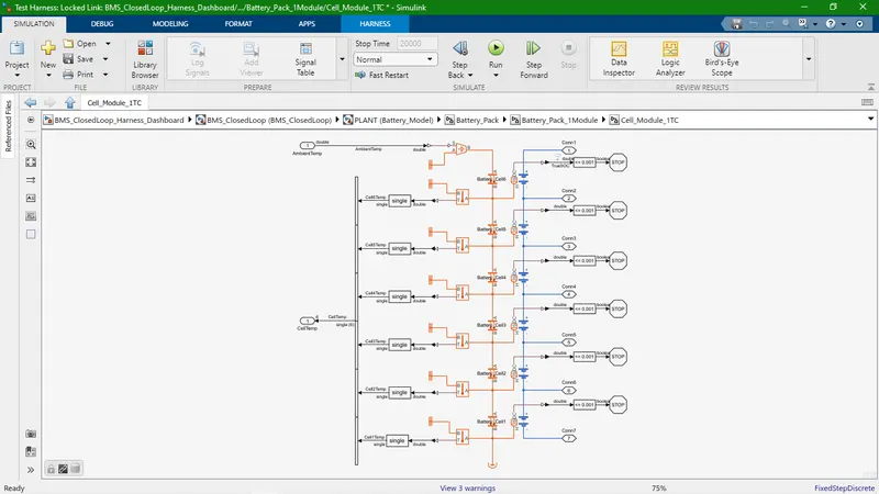
- This is 6 series cell module.
- Here, we got battery SOC, thermal system (Input is at ambient temperature and output is more than that) related information.
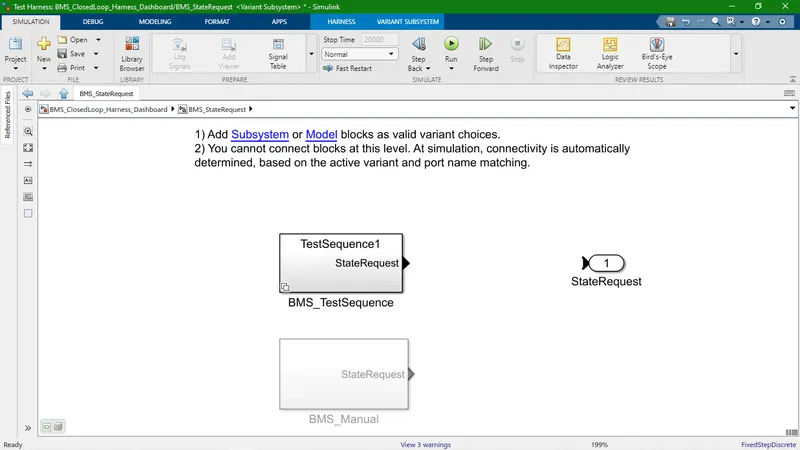
- BMS_StateRequest in two options available one is BMS_TestSequence and other one is BMS_Manual.
- It's selection button place over dashboard.
- Selecting the first test sequence we can check the conditions for this particular condition.
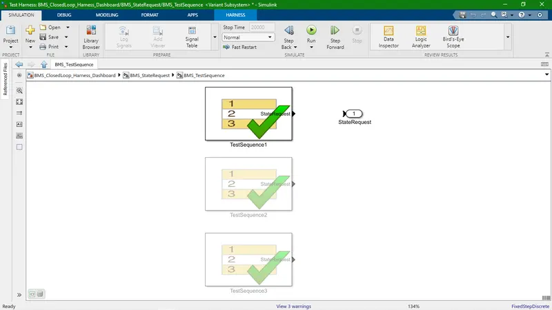
- There are three stages of driving condition, namely
- Driving
- Charging
- Standby
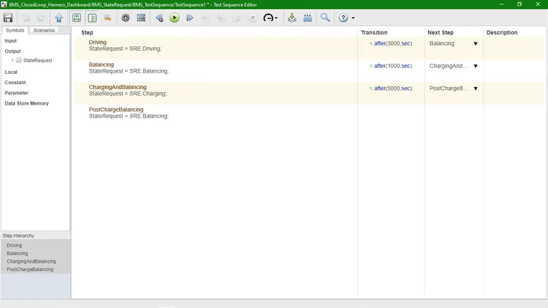
- When the simulation begins, initially the vehicle is in driving state and the SOC will decrease for this time period. After a time period of
3000 seconds the next step is balancing mode and the vehicle is in standby condition. After, another 1000 seconds, the vehicle is in
charging phase and the battery's SOC increases almost to 100%. The next phase is the postcharging phase in which the vehicle again
goes for the standby mode.
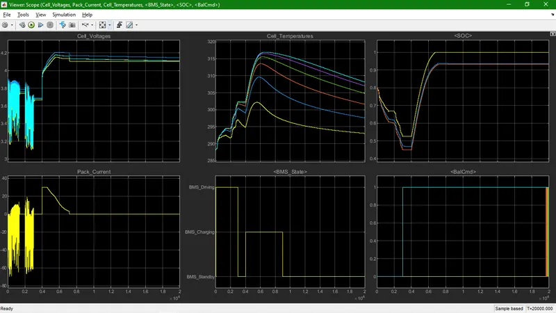
- Driving condition 1 : BMS Balance (Driving + Charging)
- The input cycle can be seen in the BMS_State plot in which the vehicle initially undergoes driving, then charging till SOC= 80% and then later in standby state.
- The SOC drops to less than 50% after the driving cycle and then later put into charging until SOC Reaches 90 to 100%.
- The Cell temperature increases during the driving and charging cycle and starts falling off in standby mode.
- The Cell temperature is increased till CC Charging and that it's goes down.
- The Cell Voltage is nearly 3.9V to 3.2V during CC Charging of the Battery cell and then it's increased nearly 4.2V with little fluctuation.
- The Current supplied to the EV during driving phase can be seen in the current plot.
- BMS State is first driving with little standby, second charging and then standby for long time.
- Supplied current at starting point is zero and then there was oscillate while CC charging. At CV charging it goes down later it's value is zero.
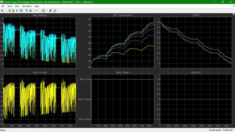
- Driving condition 2 : BMS Driving
- The input cycle can be seen in the BMS_State plot in which the vehicle undergoes driving condition.
- During Charging the Battery pack voltage is increased upto 3.9V.
- The Cell SOC drops 80% to nearly 0%.
- The Cell temperature is increased while CC Charging and it was increased more than 30 degree.
- The Cell Voltage is nearly 3.9V to 3.1V during CC Charging of the Battery cell.
- The Current supplied to the EV during driving phase can be seen in the current plot.
- Supplied current at starting point is zero and then there was oscillate while CC charging.
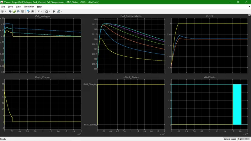
- Driving condition 3 : BMS Charging
- The input cycle can be seen in the BMS_State plot in which the vehicle undergoes charging condition.
- The Cell SOC is grow and reached at 90 to 100%.
- The Cell temperature is increased while CC Charging and it was increased more than 30 degree.
- At starting BMS Charging current is suddenly goes up and reach at peak point and then came back to zero.
- The Cell Voltage was nearly 3.9V at starting point and instantly climb-up till 4.2V and then it was reduce.
2.What is coulomb counting? Refer to the above model and explain how BMS implements coulomb counting for SOC estimation ?
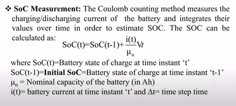
- Coulomb counting is a technique used to track the State of Charge of a battery pack. It works by integrating the active flowing current (measured in amps) over time to derive the total sum of energy entering or leaving the battery pack.
- This is the SOC estimation block.
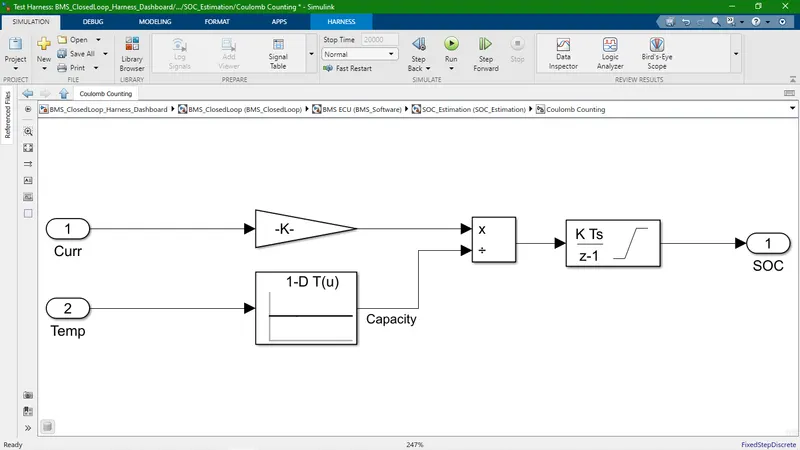
- This is the main equation which is use for calculate SOC and this is dependent on charging/discharging current.