Week 7 State of charge estimation
Aim: Study of coulomb counting for SOC estimation and testing harness for BMS.
Objectives:
01.
To study test cases from harness dashboard and write a detailed report on the results.
02.
To study, what is coulomb counting? And how BMS implements coulomb counting for SOC estimation ?
Introduction:
What is Test Harness?
Create a test-specific simulation environment for your model by using a test harness. You can isolate individual blocks for unit testing and add inputs, verification logic, and dashboard blocks. Perform closed-loop testing by adding physical plant models to the test harness. Test potential design changes in the test harness before you change the production model.
Compared to using separate models for unit testing, test harnesses offer management and synchronization capabilities in the model canvas. If your model is under change management, you can save test harnesses in external files, without changing the main model.
You can test generated code by simulating test harnesses in SIL or PIL mode. You can also test external handwritten code by creating test harnesses for C Caller or S-Function blocks.
What is BMS?
A battery management system (BMS) is any electronic system that manages a rechargeable battery (cell or battery pack), such as by protecting the battery from operating outside its safe operating area, monitoring its state, calculating secondary data, reporting that data, controlling its environment, authenticating it and balancing it.
A battery pack built together with a battery management system with an external communication data bus is a smart battery pack. A smart battery pack must be charged by a smart battery charger.
What is SoC And SoC Estimation?
The SOC is one of the most important parameters for batteries, but its definition presents many different issues. In general, the SOC of a battery is defined as the ratio of its current capacity Q(t) to the nominal capacity Q(n). The nominal capacity is given by the manufacturer and represents the maximum amount of charge that can be stored in the battery.
The SOC can be defined as follows:
`SoC = frac(Q(t))(Q(n))`
The various mathematical methods of estimation are classified according to methodology. The classification of these SOC estimation methods is different in the various literatures. However, some literatures allow a division into the following four categories.
(i) Direct measurement: This method uses physical battery properties, such as the voltage and impedance of the battery.
(ii) Book-keeping estimation: This method uses discharging current as the input and integrates the discharging current over time to calculate the SOC.
(iii) Adaptive systems: The adaptive systems are self-designing and can automatically adjust the SOC for different discharging conditions. Various new adaptive systems for SOC estimation have been developed.
(iv) Hybrid methods: The hybrid models benefit from the advantages of each SOC estimation method and allow a globally optimal estimation performance. The literature shows that the hybrid methods generally produce good estimation of SOC, compared to individual methods.
|
||||||||||||||||||||||||||||||
Table01: Different types of Mathematical methods for estimation of SoC.
What is Coulomb counting?
Coulomb counting method:
The Coulomb counting method measures the discharging current of a battery and integrates the discharging current over time in order to estimate SoC. Coulomb counting method is done to estimate the SoC(t), which is estimated from the discharging current I(t), and previously estimated SoC values, SoC(t-1). SoC is calculated by the following equation:
`SoC(t)=SoC(t-1)+frac(I(t))(Qn)*Deltat`
But there are several factors that affect the accuracy of Coulomb counting method including temperature, battery history, discharge current, and cycle life.
Modified Coulomb counting method:
To improve the Coulomb counting method, a new technique called modified Coulomb counting method is proposed. The modified Coulomb counting method uses the corrected current to improve the accuracy of estimation.
The corrected current is the function of discharging current. There is a quadratic relationship between the corrected current and discharging current of battery. By practice of experimental data, corrected current is calculated by the following form:
`Ic(t)=k2I(t)^2+k1I(t)+k0`
where k2, k1 and k0 are constant values obtained from the practice experimental data.
In modified Coulomb counting method, SOC is calculated by the following equation:
`SoC(t)=SoC(t-1)+frac(Ic(t))(Qn)Deltat`
The experimental results show that the accuracy of the modified Coulomb counting method is superior to the conventional Coulomb counting method.
Problem statement:
01.
Simulate the 3 test cases from harness dashboard and write a detailed report on the results.
02.
What is coulomb counting? Refer to the above model and explain how BMS implements coulomb counting for SOC estimation?
Solution:
01.
Simulate the 3 test cases from harness dashboard and write a detailed report on the results.
Firstly we will extract the downloaded file from the link provided in the challenge section.
Then we will open that folder in the matlab.
Later from that folder we will open the 'Battery System' model.
And we will click on 'Continue', as shown below in figure01.
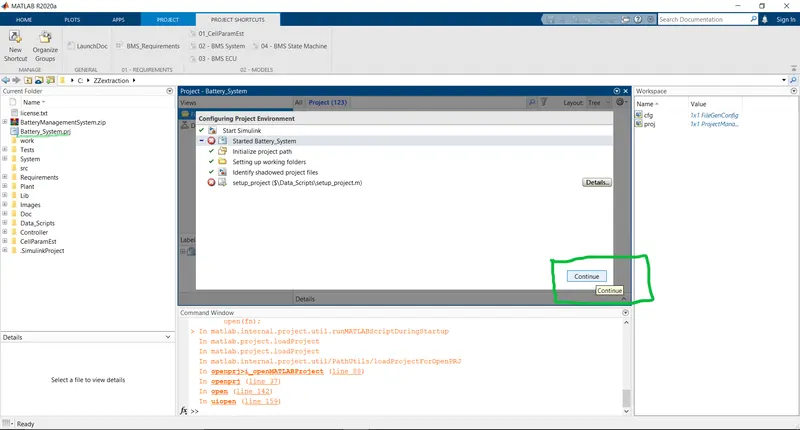
Fig01: Opening 'Battery System' model in matlab.
After that we will goto 'Tests'-'System'-'BMS_ClosedLoop_Harness_Dashboard'.
Now open the simulink file 'BMS_ClosedLoop_Harness_Dashboard' as shown below in figure02.
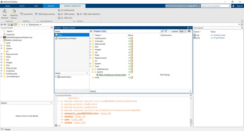
Fig02: Opening the simulink file 'BMS_ClosedLoop_Harness_Dashboard'.
After opening the simulink file 'BMS_ClosedLoop_Harness_Dashboard'.
We will get matlab models for 'Testing Harness' and 'Battery Management System' as shown below in figure03.
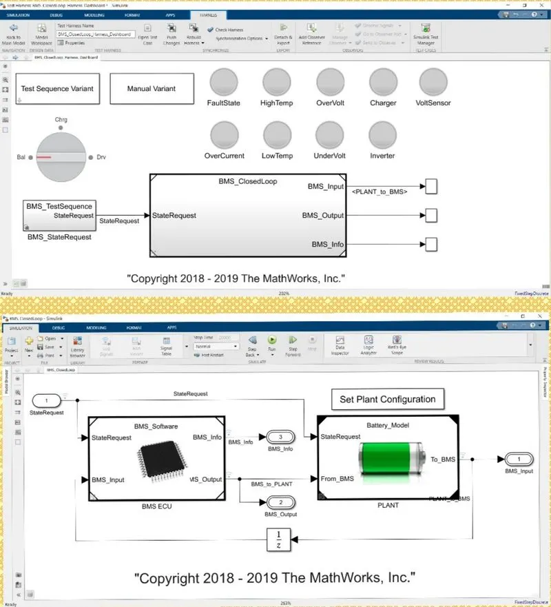
Fig03: Simulink Model interface for 'Testing Harness' and 'Battery Management System' respectively.
Firstly we study about the 'Testing Harness Model'.
Shown below in figure04 is the interface of 'Testing Harness Dashboard'.
This consists of total three tests.
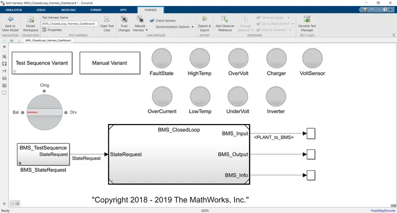
Fig04: Interface of 'Testing Harness Dashboard'.
To select one out of three tests, open the 'Test Sequence Variant' block as shown below in figure05.
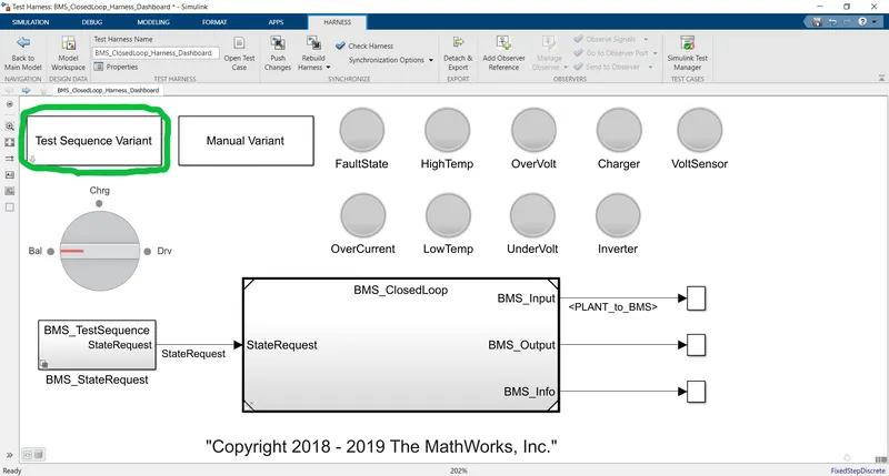
Fig05: Opening the 'Test Sequence Variant' block.
After opening the 'Test Sequence Variant' select Test number 1,2 or 3 anyone from all of three.
Click 'Apply', Click 'OK'.
As shown below in figure06 test number-01 is selected to demonstrate an example.
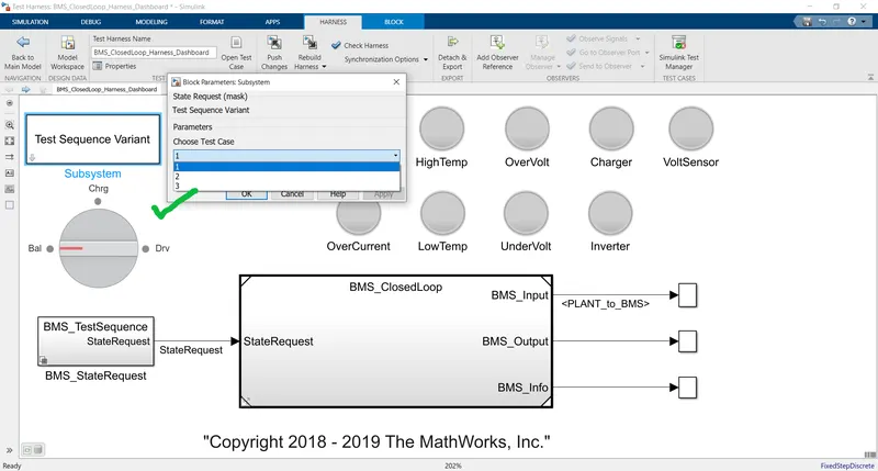
Fig06: Selecting Test number-01 from block parameters to demonstrate an example.
To check which test is selected goto 'BMS_TestRequest' block as shown below in figure07.
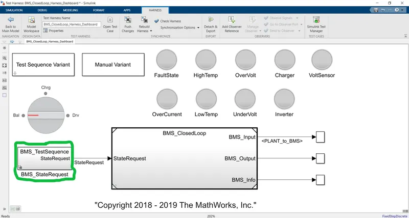
Fig07: Opening 'BMS_TestRequest' block.
Now open the 'BMS_TestSequence' block as shown below in figure08.
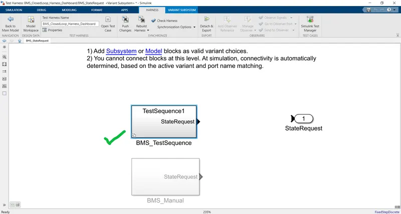
Fig08: Opening the 'BMS_TestSequence' block.
After opening the 'BMS_TestSequence' we will get the following interface to check our selected option for the test.
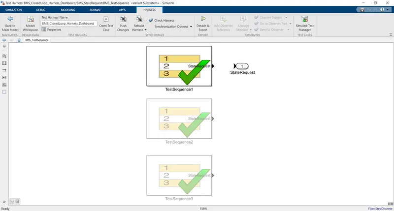
Fig09: Inside interface 'BMS_TestSequence' to check our selected option for the test.
Test-01
Fig10: Inside interface 'BMS_TestSequence' for Test-01.
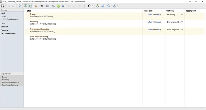
Fig11: Testing conditions and parameters for Test-01.
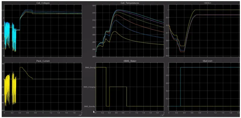
Fig12: Results for Test-01.
Test-02
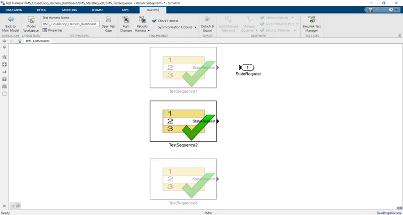
Fig13: Inside interface 'BMS_TestSequence' for Test-02.
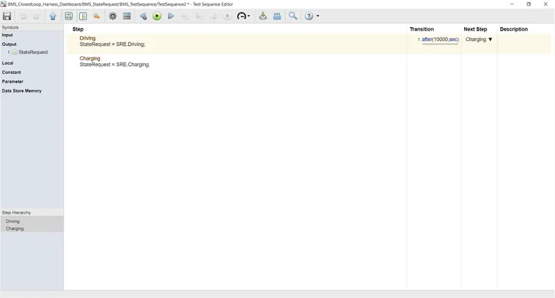
Fig14: Testing conditions and parameters for Test-02.
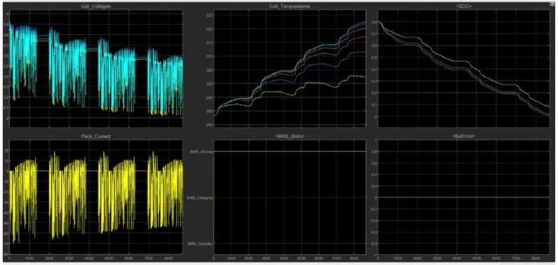
Fig15: Results for Test-02.
Test-03
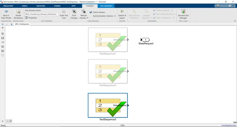
Fig16: Inside interface 'BMS_TestSequence' for Test-03.
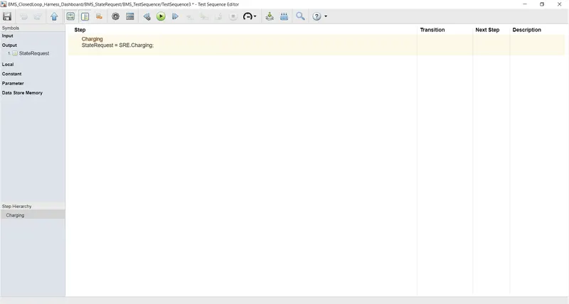
Fig17: Testing conditions and parameters for Test-03.
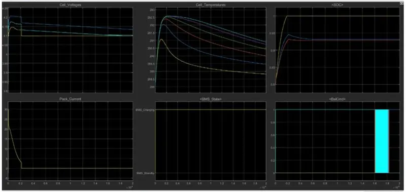
Fig18: Results for Test-03.
02.
What is coulomb counting? Refer to the above model and explain how BMS implements coulomb counting for SOC estimation?
What is Coulomb counting?
Coulomb counting method:
The Coulomb counting method measures the discharging current of a battery and integrates the discharging current over time in order to estimate SoC. Coulomb counting method is done to estimate the SoC(t), which is estimated from the discharging current I(t), and previously estimated SoC values, SoC(t-1). SoC is calculated by the following equation:
`SoC(t)=SoC(t-1)+frac(I(t))(Qn)*Deltat`
Now we'll learn, How BMS implements coulomb counting for SOC estimation?
Shown below in figure10 is the interface of the 'BMS'.
Here the input signal(StateRequest) and feedback signal(BMS_input) from the battery are fed to the 'BMS ECU' block.
Output of the 'BMS ECU' block is given to the 'PLANT' block.
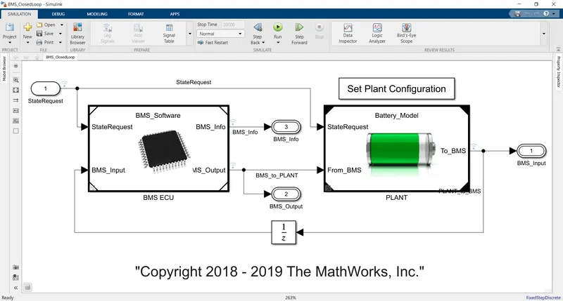
Fig19: Interface of the BMS model.
After opening the 'BMS ECU' block we will get thw following interface.
Which consists of blocks of Current power limits calculator, State Machine, Bus Management, Balancing logic and SOC Estimation connected.
Current power limits calculator sets the lower and upper limits for the values of the current and voltage for charging and discharging of the battery.
This limited current and voltages are fed as input to the 'State_Machine' block.
The 'SOC_Estimation' block is with two inputs, one from the 'PLANT' block and the second is from output of the 'State_Machine'(BMS_State_Enum) block.
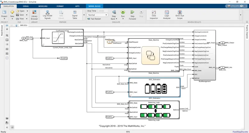
Fig20: Interface inside the 'BMS CEU' block.
Ater opening the 'SOC_Estimation' block we will get the interface shown below in figure12.
Further the input from 'PLANT' i. e. tempearture and pack current are given to the 'Coulomb Counting' block.
The 'SoC' is the output of the 'Coulomb Counting' block.
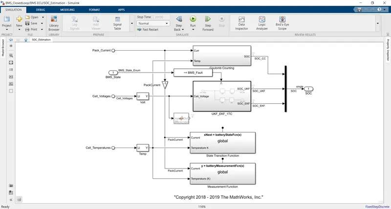
Fig21: Interface inside the 'SOC_Estimation' block.
After opening the 'Coulomb counting' block we will get the interface as shown below in figure13.
Now let's study how coulomb counting block works.
It consists of the 'Gain' block which is nothing but the value of current of the battery while charging or discharging during that particular interval time.
The capacity of the battery is represented by the '1D Lookup Table' block.
As we know, SOC can be defined as follows:
`SoC = frac(Q(t))(Q(n))`
Therefore according to the defination of SoC product block is provided.
Further this ratio(SoC) for unit of time is integrated over a period of time therefore 'Discrete-Time Integrator' block is provided to calculate SoC added or subtracted during charging or discharging respectively.
Further this value of SoC is added or substracted from the previous value of SoC of the battery to get the latest value SoC of the battery.
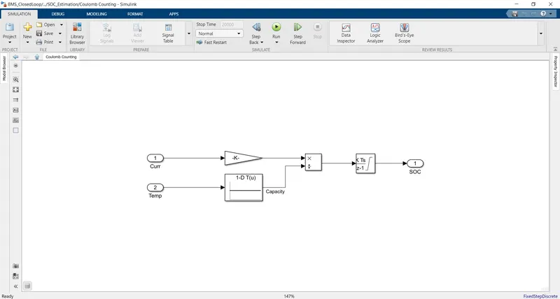
Fig22: Interface inside the 'Coulomb counting' block.
Conclusion:
In this study we learn the concept of testing of the battery using 'Testing Harness' and the Estimation of the SoC of the battery using the concept of coulomb counting.