Week 7 State of charge estimation
Introduction to Battery Technology for Electric Vehicles using MATLAB & Simulink
Week 7 State of charge estimation
Q.What is coulomb counting? How BMS implements coulomb counting for SOC estimation?
Ans=>
- Coulomb Counting
Coulomb counting is a technique used to track the State of Charge of a battery pack. It works by integrating the active flowing current (measured in amps) over time to derive
the total sum of energy entering or leaving the battery pack. This produces a capacity that is typically measured in Amp-hours.
- Coulomb Counting Method:
But there are several factors that affect the accuracy of Coulomb counting method including temperature, battery history, discharge current, and cycle life.
Here a coulomb counting method for state of charge estimation for lithium-ion batteries and its hardware implementation of this algorithm was performed
on an MCU (PIC18F) and validated by test.
Li-Ion Batteries requires a specific charge method which consists on the constant current-constant voltage (cc-cv) charging algorithm . Also these batteries type have
specific behaviors such as the different discharge gaits under different currents and the selfdischarge characteristic.
So battery monitoring is one of the most important challenges facing Li-Ion batteries
in order to monitor these behaviors. State-of-charge (SOC) estimation is the crucial task in battery monitoring.
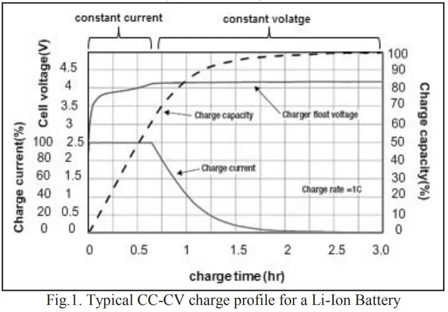
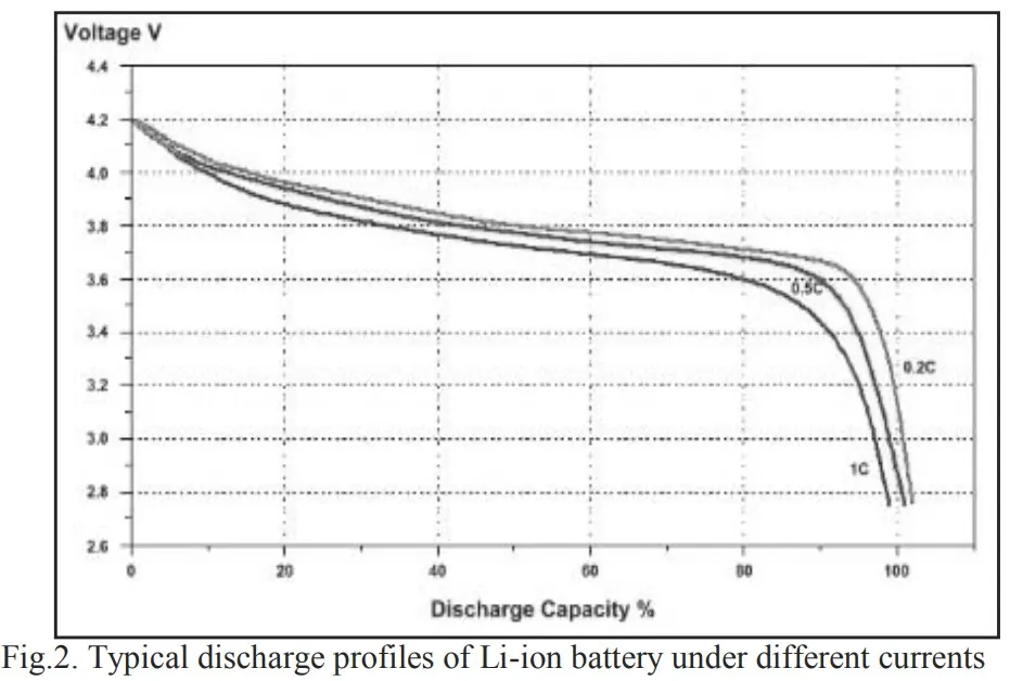
Accuracy in SOC knowledge can avert batteries from coming in over-charge and deep-discharge and these states may cause irreversible damage to the battery’s internal structure.
Many methods were proposed for the batteries SOC estimation:
In fact three main types of methods are identified: electrochemical methods, electrical methods and adaptive ones.
1. The electrochemical methods in spite of their high accuracy are judged difficult to implement neither on software nor on hardware solution because
of the need to access to the chemical structure of battery .
2. Adaptive methods require an equivalent model and a resolution algorithm such as neural network , Kalman filter , fuzzy logic algorithm and state observers .
So accuracy of these methods depends on the efficiency of the battery model.
3. Unlike previous methods, electrical ones require only parameters that are obtained by measurements such as terminal voltage, current and internal resistance.
Among these electrical methods, coulomb counting based on current integration remains one of the most
widely used method due to its implementation simplicity and low complexity.
Assuming that the initial value SOC (t0)is known,
instantaneous SOC is generally evaluated by integrating the
battery current over time, as shown in equation
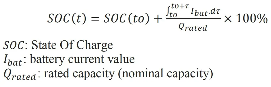
The coulomb counting method consists on exploiting the relation by quantifying the charge delivered by the battery through sensing its input and output current .
However there are some inefficiencies when using this method; first of all, the access to the initial SOC which is not guaranteed, secondly self-discharge may distort the real SOC
value after a long storage period and finally the reference capacity Qrated which must be updated in terms of aging battery degradation.
Enhanced coulomb counting method takes into account self-discharge losses and requires a recalibration at fully and empty stages in order to
determine initial SOC and update the reference capacity to have a 100% maximal SOC value.
The flowchart given in Fig.3 explains the algorithm used to manage the battery monitoring by switching from a battery operating
mode to another in accordance with the transitions conditions.
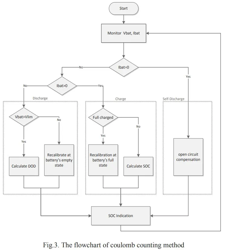
The estimation of the SOC of a Li-Ion battery in this method is based on monitoring both the voltage Vbat and the current Ibat.
The operation mode of the battery is recognized by the direction of current through the battery system.
When the battery is in open circuit mode, Ibat = 0 and compensation of self-discharge losses will be taken into account as explained .
The information needed to carry monitoring are the measurement of the battery voltage, the current flowing through it and the operating temperature.
Coulomb counter ∆Q is used to track the SOC when the battery is charged or discharged.
The amount of charges ∆Q in an operating period  is obtained by a temporal integration
of a measured charging/discharging current Ibat like expressed:
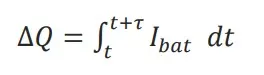
This variance ∆Q that will be used in the following equations is negative if the battery is in discharge, positive if in charge.
A. Charge Mode
In this mode, the coulomb counter is presented by Qgained as
expressed in (3), which represents the quantity of charges
accumulated during .

So the variation of the state of charge gained in this same operating period is obtained by the relation
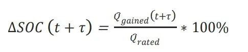
By cumulating the previous state of charge indication and the obtained one we can have the instantaneous value of SOC :

Knowing the relationship indicated in relation the value of
depth of discharge DOD is updated in every charging operation
in order to get it back every switching to discharging mode.

B. Discharge Mode
In the discharging mode the coulomb counter is presented by
Qlost, which represents the amount of charges losses in the
operating period by equation

The depth of discharge variation is calculated according to :
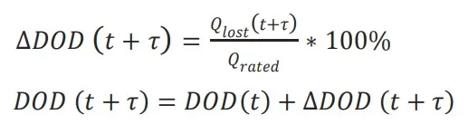
The SOC indication then is done by applying the equation.
C. Self-Discharge Mode
At the battery storage periods, the percentage of monthly selfdischarge is converted to amount discharged per hour; this
amount is designed by the constant q per/hour . Considering a
5% rate of self-discharge per month q per/hour is approximated
to 0.0016 Ah. So the quantity of charges dissipated in the open
circuit period Qoc is calculated by the equation
representing the accumulative losses during the storage hours.

h : Hour of storage
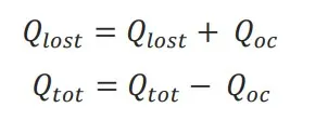
This value will be added to the amount of charge lost Qlost
during discharge mode and subtracted from the amount of
charge accumulated Qgained in charge mode as expressed in
relations. This compensation of self-discharging
loss is made at each open circuit period and before switching to
another operating battery’s mode.
D. Temperature effect
The temperature variation affects considerably the state of charge of the Li-Ion battery .
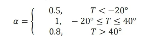
In order to improve accuracy of the battery state of charge, a temperature coefficient a is introduced and multiplied by the value of the calculated SOC.
This coefficient varies depending on the operating temperature according to the intervals variations
E. Recalibration
When the loaded voltage Vbat drop under a limit voltage Vlim(3V), during the discharging mode the battery is considered totally discharged.
When it’s empty, the battery can no longer be used and should be recharged.
So after a cycle of charge/discharge a recalibration should be made of Qmax which represents the maximum capacity that can be released by the battery.
This recalibration allows rectifying the indication of SOC by replacing Qrated by Qmax in relation .
Also we recalibrate the State-of-Health (SOH) of the battery SOH defined is relation as:

nc = number of cycles
Moreover, the battery is fully charged. Then SOH should be updated by assigning the quantity of charges releasable from the battery to Qmax.
The SOH indeed represents the ageing degree of the battery; in fact it’s at 100% maximum value when the battery is new.
When the battery is getting old and Qmax became more and more inferior than Qrated , SOH value drops to indicate the health degradation of the battery.
-IMPLEMENTATION
The adopted coulomb counting algorithm for SOC estimation was implemented on hardware platform.
Monitoring functions include the measurement of the battery voltage, the current flowing through it
and the operating temperature by the 10 bits Analog to Digital Converter (PIC18F).
-Measurement
Battery parameters detection is one of the most important issues in control and management of a battery management system .
It includes cell voltage measurement, current detection and temperature detection. Estimation of SOC and other battery states imposes high requirements on cell voltage precision .
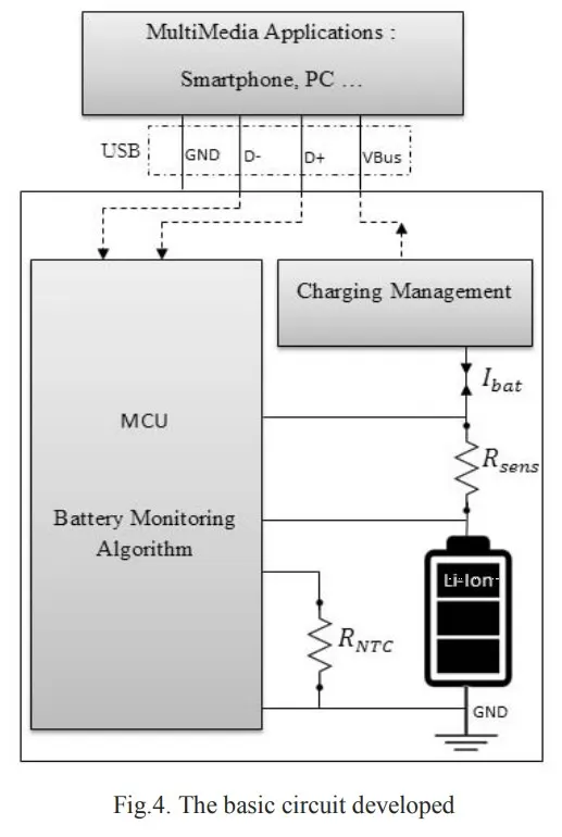
In order to measure the voltage and the current with which the battery is charged or discharged, a resistor is placed in series with the battery.
The voltage value is obtained by a measure of the voltage across the battery, and a difference between the voltages at the two terminals
of the resistor will derive the current value, knowing the value of the resistance.
The external temperature is measured using a negative temperature coefficient resistor RNTC.
The diagram presented in fig.4 includes different modules connection to the data acquisition system.
The transmission of battery electrical parameters is ensured by a USB connection between the multimedia application (Smartphone, PC…) and the MCU (PIC18F).
-Application
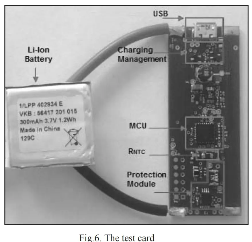
In order to validate the developed algorithm, the tests were achieved using a test card developed in IntelliBatteries,
it consists of five main parts which is shown in Fig.6:
- The charging management that ensures the battery charging with the cv-cc procedure.
- The MCU that contains the programmable card PIC18F.
- The NTC resistor that measures the local temperature of the battery.
- The protection module that protects the battery against overload, voltage drops, power surges.
- USB connection that ensure both charging process and data transmission from the multimedia application to the MCU.
The monitoring algorithm is then implemented with embedded C language on the MCU using MATLAB®X IDE. It lists the functions used
in monitoring the state of charge of the battery.
-Validation
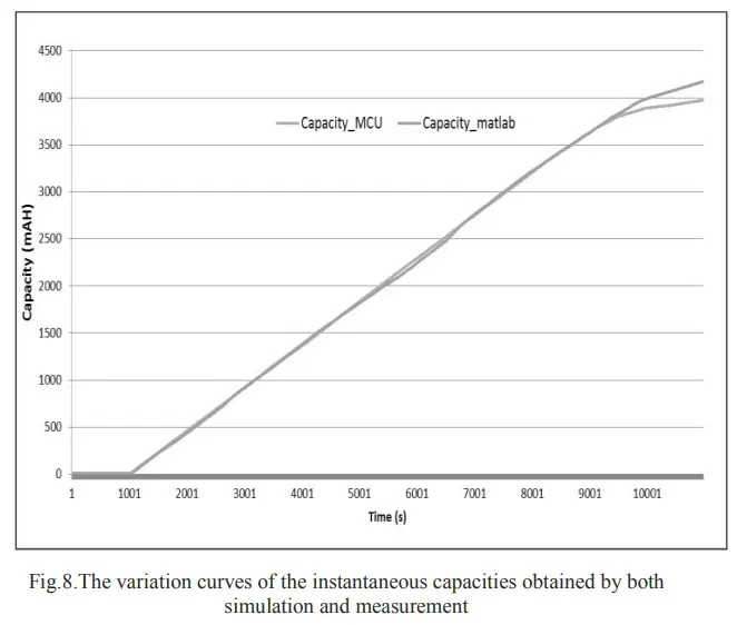
The test based on comparison between the coulomb counting algorithm simulated by Matlab and the algorithm embedded on the MCU for charging mode.
Despite the difference detected between the two curves for the same algorithm with the same data which is due to that MATLAB is a high-precision calculator
while the MCU has an ADC of only a resolution of 10 bits, this illustration proves the reliability of the developed system since the two curves are nearly superposed.
-REFERENCE:
2015 12th International Multi-Conference on Systems, Signals & Devices
Implementation of a Coulomb Counting Algorithm
for SOC estimation of Li-Ion Battery for Multimedia
Applications
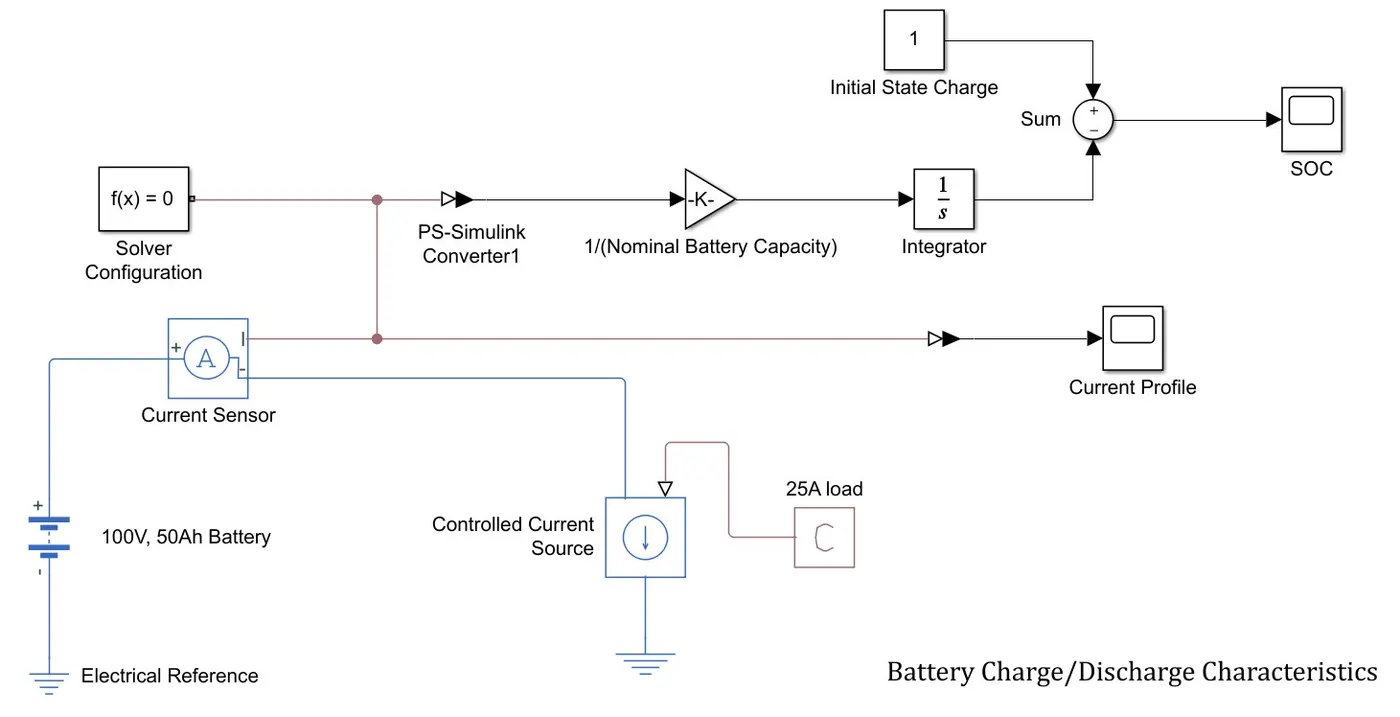
For typical example of how we can implement Coulomb counting in Simulink model as follow:
Model of battery system with constant load demand
Constant input model
Here we use a constant value for making the battery discharge.A PS Constant block of 25A constant load applied to battery.
In here the current controller arrow should be downward facing, to obtain a discharge characteristic from the model.
If the arrow points upward the battery shows a charging nature.
Description & Configuration of Model
This model shows a high-voltage battery circuit that can be used to power an Electric vehicle. The battery is configured with a nominal voltage value of 100v and 50A current.
The dynamic model has a signal builder as dynamic drive cycle load The constant model has a Constant block with the value of 25 as the load.
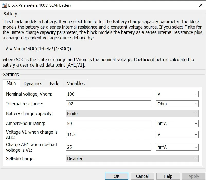
The total simulation time is 3600 seconds (60 seconds x 60= 60 minutes=1hour). The current controlled source supports the load demand.
The current sensor senses the current usage from the dc link here. In case of vehicle modelling, this current sensor senses the current and provide to power the Electric Motor.
The initial state of charge of battery is taken as 1 using a constant block. The gain value can be taken as 1/nominal battery capacity
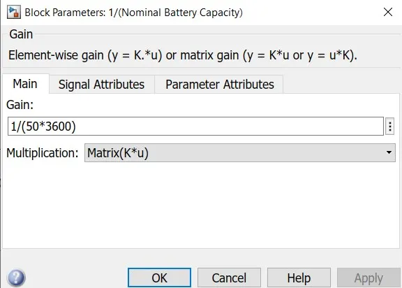
Configuration of Gain block
The integrator helps to accumulate all input signals and give a corresponding plot in the scope.
The gain value is taken as 1 in the discrete integrator block. Scope displays the results or plots for a circuit.
The Solver Configuration block specifies the global environment information and provides parameters for the solver that your model needs before you can begin simulation.
Results analysis
The results from the model is given below
State of charge of battery from scope
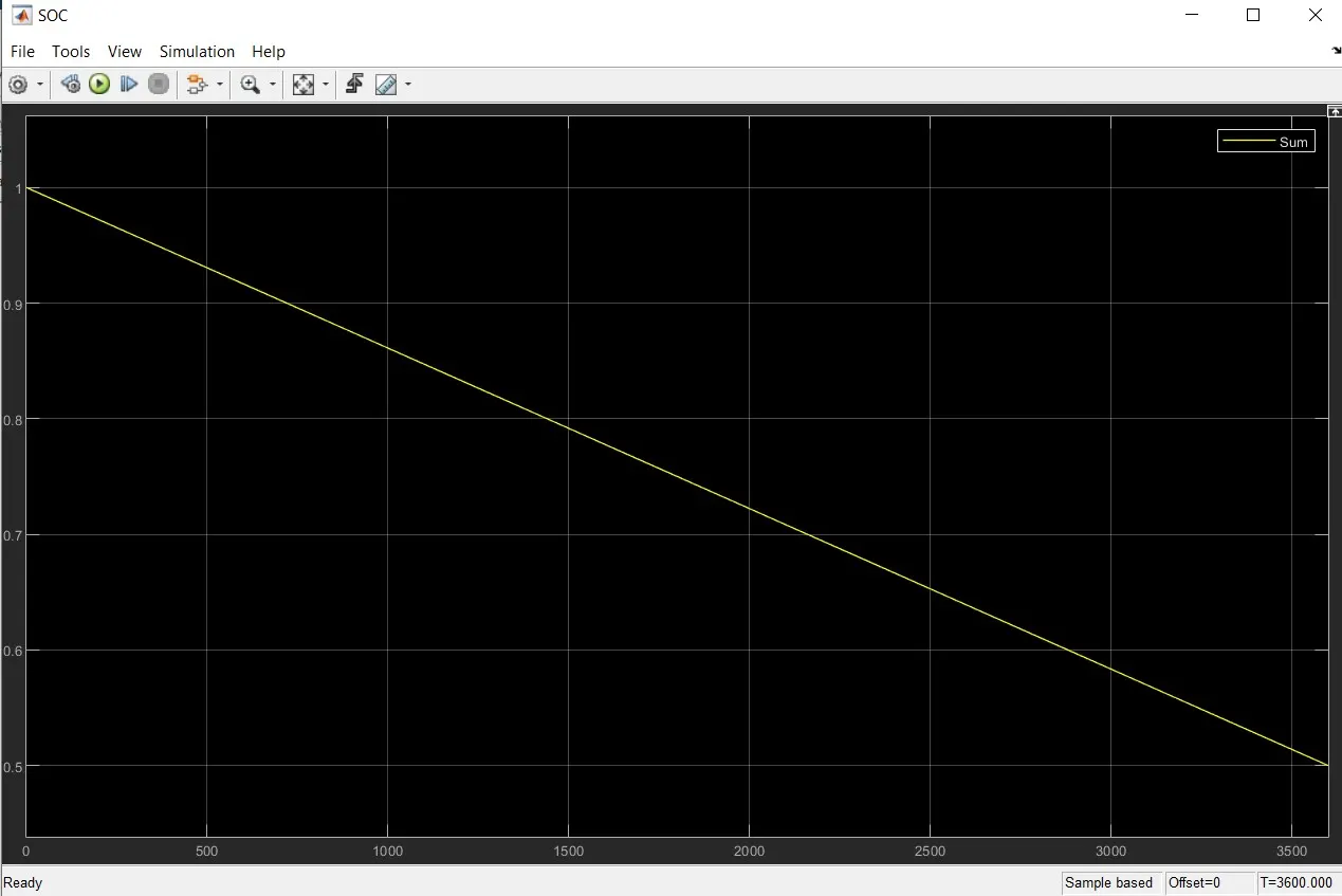
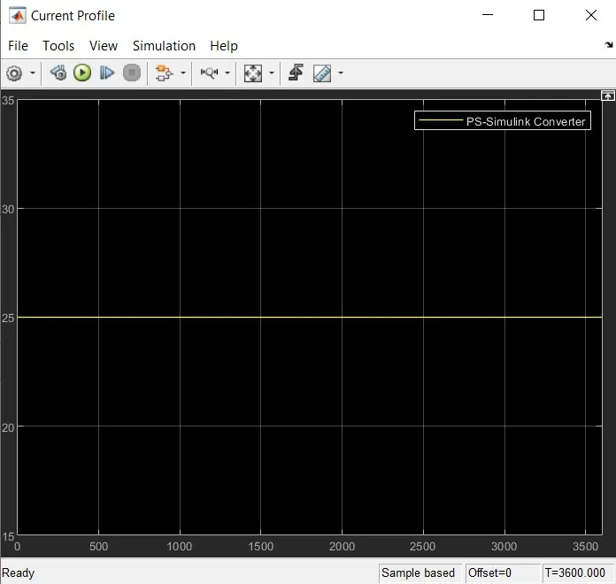
The charge removed from the battery for 1 hours is around 25 A. This follows the input values we have given.
The plot shows that the state of charge of battery is initially 1 (100%) and it is decreasing according to the load demand given .The simulation time was given as 3600s (1 hour).
- B HThanks for this excellent very detailed article on the enhanced method for CC. I am actually doing the exact topic for my research university project but need some of help with the doubts I am having . Firstly, I am going to use a Rasberry PI 4 instead of a microcontroller to do the calculations. Speaking of it , is there way to have a code reference to begin with as I am thinking to write Python code for doing all the SOC calculations. Secondly, I am still confused with the fact of the initial SOC to begin with . suppose I start with a new LFP battery pack (4s cells) which I ensured is fully charged. in that case should the initial SOC be 100% (or 1) ?. what if I use a battery pack which isnt new , how will I have a beginning value for it since having the wrong initialization will render me wrong results from start itself of the program. Also regarding the SOH which will dictate the newer Capacity , how is this logic implemented here ? what if the battery pack I use is fairly used then how will it update the current Capacity of it so for to account the aging effects? About the temp coefficient that depends on the temp ranges, how is it implemented? I mean here how the values are derived based on various ranges. Is there any formula used or any scientific research etc? Lastly, Thank you very much for your time and patience and I hope to get a positive response from you soon Best Regards, Hassan